Breadboard Basics: What They Are, How They Work, and How to Use Them
What They Are

A Funny-Looking Thing
If you’re new to the world of electronics you might have seen a funny looking thing that is used extensively in the electronics community. It has no batteries, no doo-dads, buttons or cords. On its own it is totally isolated from any electrical energy, but can quickly be given some jumper wires, some through-hole components, and be connected to a power source to build a functioning circuit in a fraction of the time of soldering them or connecting them in another way.
It’s Breadboard, Not Bread Board

Breadboards are a type of electronics tool used to prototype circuits. They are made up of multiple pin holes called points that are internally connected via metal conductors, both horizontally and vertically. To make connections, you just push the leads of through hole components into the points.
They are named either breadboard or prototype breadboard, as opposed to prototype board which usually refers to a much thinner board that has solderable copper contacts on them to make component connections. Breadboards are also distinguished from bread boards because you don’t slice bread on them.
- Breadboards: used for making prototype electronic circuits.
- Bread boards: Used for slicing and serving delicious breads.
A Variety of “Breads”
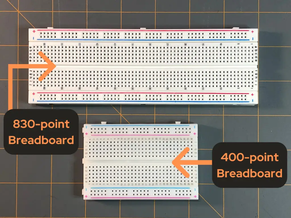
Prototype breadboards come in many shapes and sizes with a variety of a number of pin holes or points, but for our discussion we will refer to a typical 830 point rectangular breadboard. The number of points doesn’t matter too much, unless you’re using a lot of components in your prototype circuit, then of course, you’ll want a larger breadboard or multiple breadboards to allow for more points to work with.
How They Work: Using the Football Stadium Analogy
The Field
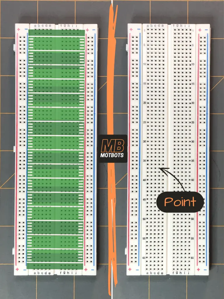
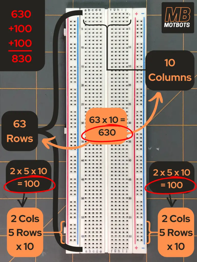
To use a breadboard, you must know the orientation and connection of the holes or points of the board. To help in our understanding of the prototype breadboard, let’s use the analogy of an American football stadium. The interior section of the breadboard can be thought of as the field, like where the players play. This section consists of points that have metal contacts in them that connect the holes horizontally, each horizontal row being labeled with numbers – kind of like the number markings on a football field. Note that the columns are labeled with letters of the English alphabet. For example, each row consists of 10 holes labeled from a-to-j. There are a total of 63 rows, therefore making 10×63 = 630 holes or points.
You can see from the image below that there is a center groove that divides the rows in half. Looking at row 1 for example, you can see that the 10 holes or points start with 5 from a-to-e, then there’s the center groove in the breadboard, then the other 5 points from f-to-j.
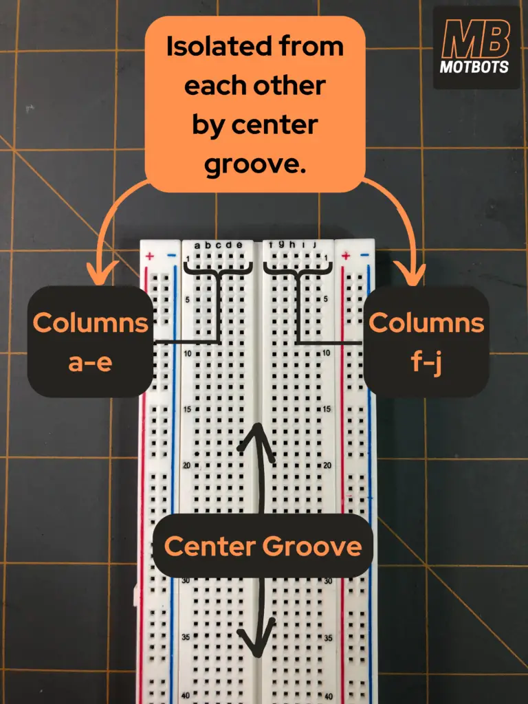
This dividing groove lets us know that the rows are not connected from one side of the groove, points a-to-e, to the other side of the groove, points f-to-j. In other words, points a-to-e are connected to each other in a row, but are isolated from points f-to-j in that same row, and vice versa. This is true for every row, from row 1 to 63.

The Stands
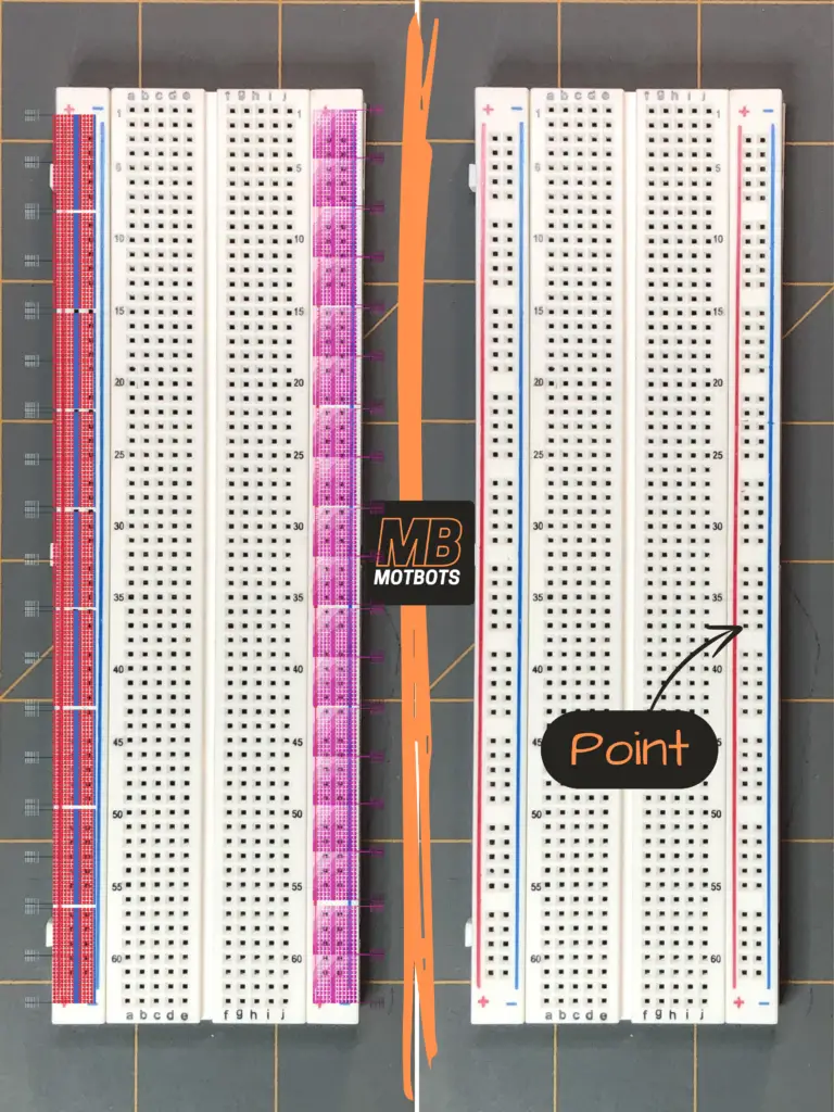
If you look at the breadboard carefully, you’ll notice that on either side there’s a slender part of the board that has a red and blue line running all the way down its surface with vertically aligned holes or points running all the way down the board. We can think of these sections of the breadboard as being the stands in the football stadium. Just as the fans in a football stadium are isolated from players on the field, so too are the holes or points on the left and right edges of the board isolated or separate from the points on the interior section of the board.
Looking at these outer edges, you’ll see there’s also a red plus symbol (+) and a blue minus symbol (-) on either end – top and bottom. These represent the positive side column and the negative side column, respectively.
Note that just as the rows of points in the interior section of the breadboard were isolated into halves, so too are the vertical points isolated into halves on the two outer sections of the breadboard.
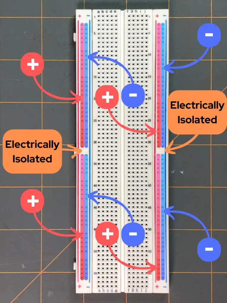
The two vertical columns of points on the outer sections of the breadboard contain 50 rows of 2, or 100 points. Again, each column of points are isolated, meaning every row of 2 points are not internally connected.
Looking closely at the outer sections of the breadboard we can see a pattern of 5 rows of 2 divided 10 times on each side of the board. That’s still 5×10 = 50 rows on each left and right outer edges of the breadboard, as explained before. If we count 5, 5 row sections of 2 down, or 25 points down, or half-way down, these top 25 rows of 2 are isolated from the bottom 25 rows of 2.
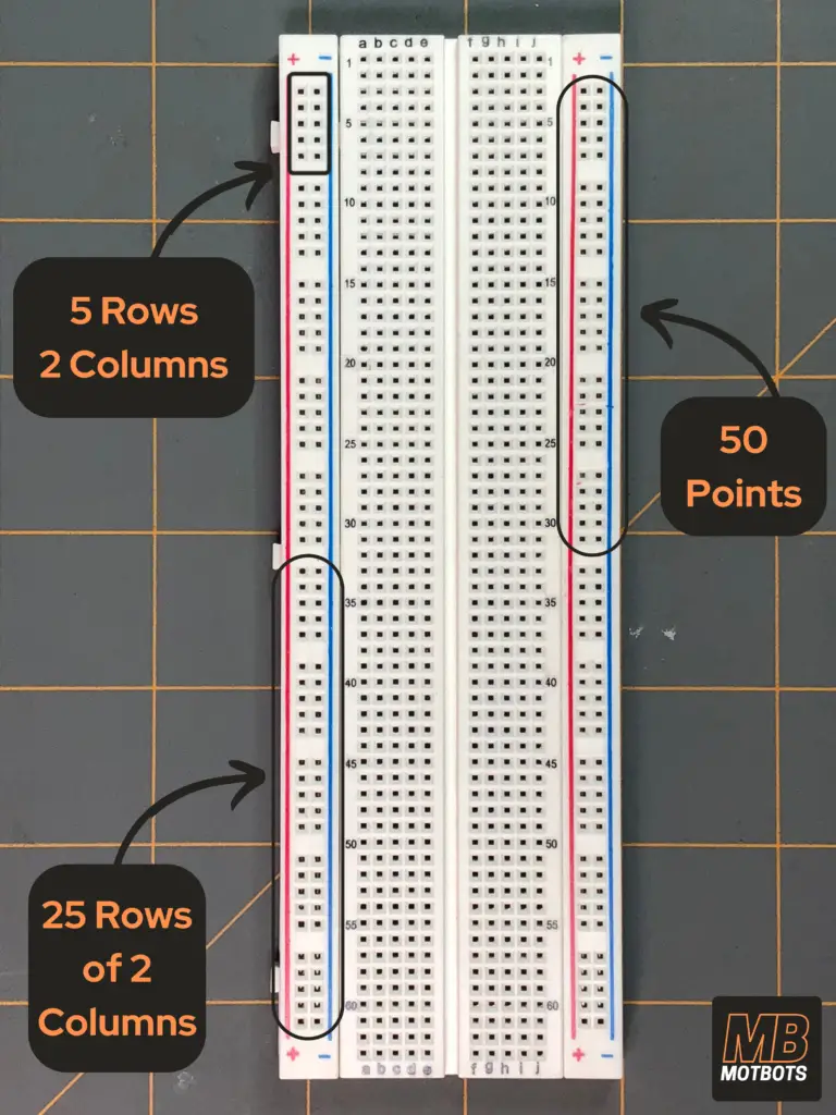
- In other words, the upper 25 points of the positive column (+) are not internally connected to the lower 25 points of the positive column (+).
- But the upper column of 25 points in the positive column (+) are internally connected and the lower column of 25 points in the positive column (+) are internally connected.
- The upper 25 points of the negative column (-) are not internally connected to the lower 25 points of the negative column (-).
- But the upper column of 25 points in the negative column (-) are internally connected and the lower column of 25 points in the negative column (-) are internally connected.
- This is true for both the left outer edge and right outer edge of the breadboard.

Using our football stadium analogy, we compared the outer sections of the breadboard as being like the stands, where the fans sit. Just like a football stadium’s divided fans, the stands on one side of the stadium are isolated from the stands on the other side of the stadium. Similarly, the left outer section of the breadboard is isolated from the right outer section of the breadboard. Both sides are isolated from the interior section, just as both stands in the football stadium are isolated from the field.
How to Use a Breadboard
Making the Connection—Understanding by Example
Let’s learn how to use a breadboard by putting together a simple circuit to show you how a breadboard works and how to properly use one. For our example circuit, you’ll need the following items:
Parts List
| Item | Quantity | Description |
| 830 Point Prototype Breadboard | 1 | Used to easily connect components without the need of soldering. |
| Jumper Wires | Multiple | Used to make connections between components on the breadboard. |
| 9V Battery | 1 | Used as a source of power for our circuit. |
| 9V Battery Snap Connector | 1 | Used to be able to connect the 9V battery easily to the breadboard. |
| DC Power Supply | Optional | An alternative to a 9V battery to use as a source to power our circuit. |
| 680Ω Resistor | 1 | Used to limit the current to the LED. |
| Green LED | 1 | Used as a light indicator to show when the circuit is ON or OFF. |
Making Our Busbars
First, let’s make our breadboard’s positive and negative busbars. Essentially, we want to connect all our negatives together and all our positives together:
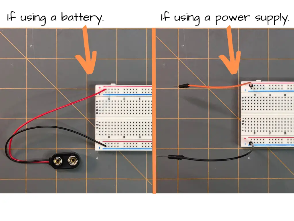
- To begin, we want to connect some type of power supply to our breadboard to be able to power our circuit. We can easily do this by simply adding a jumper wire to one side of the breadboard at the last point of the positive vertical points under the plus symbol (+) as shown in the image:

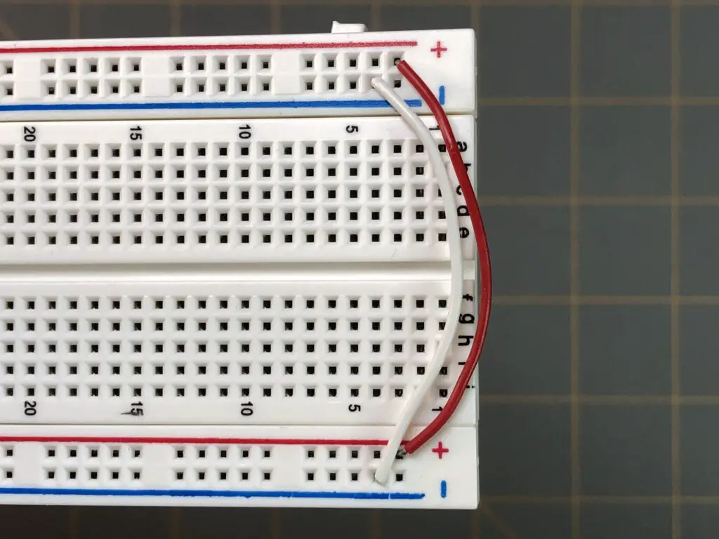
- Next, we can add another jumper to the other side of the breadboard at the last point of the negative vertical points under the minus symbol (-) as shown in the image below:
- Now, let’s go ahead and make it to where both sides that are negative are all one connection and both sides that are positive are all one connection, as shown:
- Now we’re ready for our power supply, but we’ll hold off connecting it for now.

Connecting Components
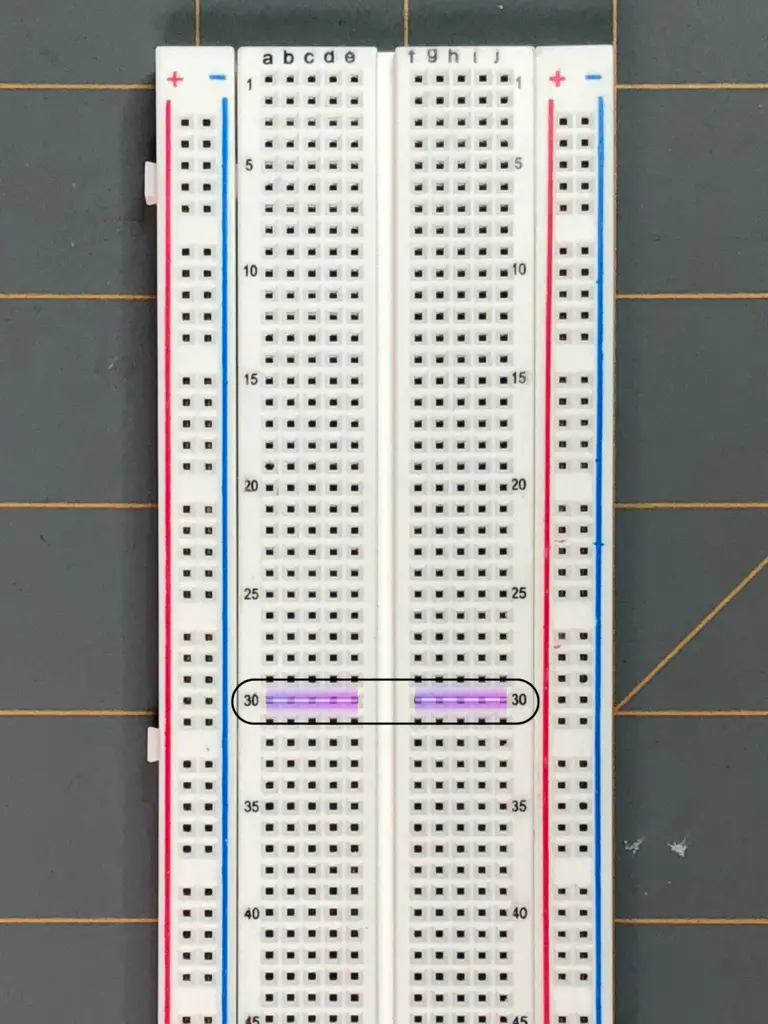
Let’s look at row 30 in the interior section on the 830 point breadboard. All the holes or points in row 30, from a-to-e are internally connected. All the holes or points in row 30, from f-to-j are internally connected, but points a-to-e are not connected to points f-to-j.
- Points a-to-e are connected internally by a metal contact.
- Points f-to-j are connected internally by a metal contact,
- but points a-to-e are isolated from points f-to-j. They are not internally connected to one another.
- This is true for every row of points in the interior section of the breadboard, from row 1 to row 63.
The Wrong Way
If you look at the image below, you can see the breadboard has been prepared as we have discussed. Now we’ll proceed to make our circuit, but we’ll purposefully connect one component in the points on the breadboard incorrectly, so we can demonstrate that if you do, what goes wrong.
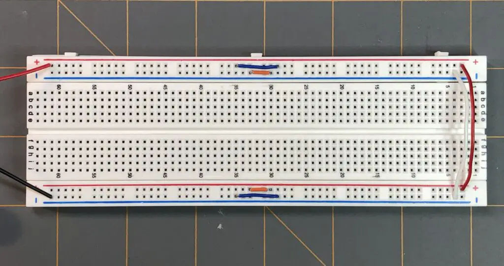
Do not connect your battery or power supply to the breadboard before connecting your components to the breadboard.
- First, take your resistor and connect one lead of the resistor to a positive point near row 30, then connect the other lead of the resistor to point a in row 30.

- Next, take your green LED and connect the anode (+) to point e in row 30 and the cathode (-) to point f in row 30.
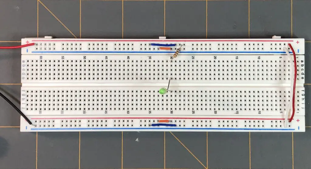
- Now, take a jumper wire and take one end of it and connect it to point j in row 31 and connect the other end of the jumper wire to a negative point on the bus-bar.
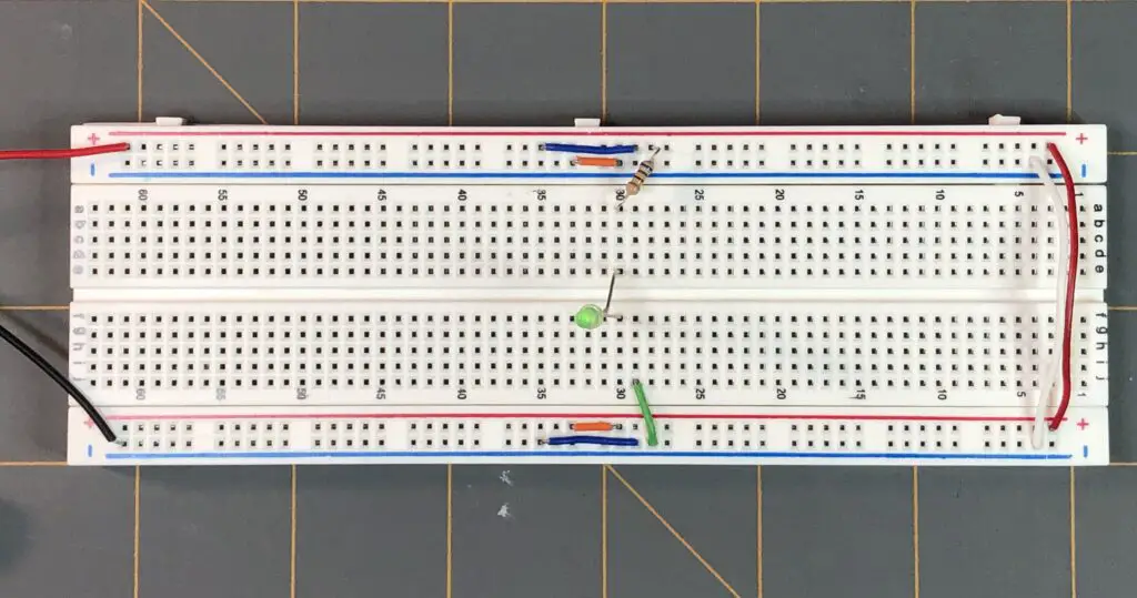
- Finally, connect your battery or power supply to the positive and negative jumper wires on our bus-bar. Make sure you have the correct orientation of polarity for your battery or power supply to the jumper wires of the bus-bar. Positive terminal of the power supply to positive jumper wire and negative terminal of the power supply to the negative jumper wire.

What happened? You might have noticed that nothing happened. The green LED did not come on! Why is that? Well, let’s explain in our next attempt to connect our circuit using the breadboard the correct way. Before we proceed, go ahead and disconnect your power source from the circuit.
The Correct Way
We connected all our components to the breadboard, and everything looked OK, but when we connected the power supply nothing happened. Did we miss something? Did we forget a jumper wire somewhere? Did we install our LED in the wrong orientation? The answer is no, to each of those.
Remember how we mentioned that the rows of the points in the interior section of the breadboard, the football field in our football stadium analogy, are connected to each other internally? Also, do you remember that we said that each row of 10 points are divided in two? Columns a-to-e in row 30 are internally connected, but are isolated from the internally connected part of the row under columns f-to-j.
- We see that we connected our resistor from a positive point on our positive bus-bar to point a in row 30. That’s OK.
- Next, we see that we connected the anode (+) lead of the green LED to point e in row 30. That’s good, because the anode or positive lead of the LED is connected to the positive facing side of the circuit and it’s also connected in line with our resistor in row 30 on the half of the row under columns a-to-e, which is what we want, because that half of row 30 is internally connected.
- We see we connected the cathode (-) lead of the green LED to point f in row 30. Now we’re in the home stretch. We just need to complete the circuit from the cathode (-) lead of the green LED to the negative terminal of our bus-bar.
- We see that we took a jumper wire and connected one end of it to point j in row 31 and connected the other end of the jumper wire to a negative point of our negative bus-bar. But wait, we didn’t connect the one end of our jumper wire to row 30! Connecting the jumper wire to point j in row 31 only connects it to the half of row 31 under the columns f-to-j!
What we essentially have is an open circuit, because we have not completed a path for the current to flow from the positive side of our circuit to the negative side of the circuit. There is a jump in our breadboard circuit at the cathode (-) of the green LED to the jumper wire connected to the negative point of our negative bus-bar. They are not connected to each other!
To fix this issue, all we need to do is move our jumper wire end that’s at point j in row 31, to point j in row 30 to complete our circuit. Once you’ve done this, connect your power source back to the circuit. Remember your polarities!
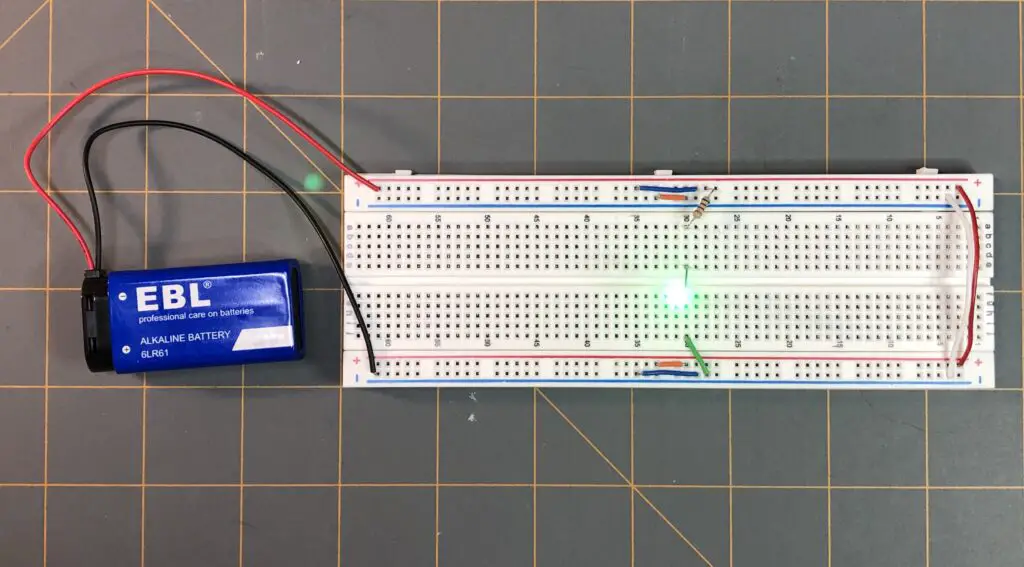
At this point, your green LED should be on. SUCCESS! You’ve learned how to use a breadboard! You’re now ready to take over the world! A breadboard is a great tool to have in your electronics toolbox. Breadboards allow you to prototype your electronic designs on the fly without all the fuss of soldering. Just don’t try to cut your loaves of bread on it.
