Introduction to PIC Programming Using C: Programming a Super Simple LED Switch – Part 3: The Code
| Project Name: | Introduction to PIC Programming Using C: Programming a Super Simple LED Switch – Part 3 |
| Project Description: | In Part 3, we get into the code for programming the PIC and discuss other topics of interest. |
| Project Difficulty: | Easy to Moderate |
| Project Note: | Attempting this project requires some hardware and software to program a PIC microcontroller. You may observe what we’ll need here, and the parts list here. |
Introduction
Welcome! In the proceeding topic, our goal is to learn how to program a PIC18F4525 microcontroller using the C programming language to control an LED with a couple of switches. It is my goal to help guide you to do this in a way that I learned from a terrific book I purchased some time ago of which you can observe for yourself at the Book Reference at the bottom of this page.
The following is intended to be an enhancement to such pedagogical material that sometimes leaves more to be desired for the reader. It is the intention of the following to add more input to the learning material that is currently available, or currently unavailable, in the market today on learning how to program a PIC microcontroller using the C programming language.
This is Part 3: The Code
This is a three part series. This is Part 3. I’ve divided this content into three parts because there was so much information to share with you that having it all on one page may have been overwhelming. I don’t want you to feel overwhelmed.
This should be a fun and exciting topic, not an intimidating one.
In Part 1, we went over all the preliminaries for knowing what a PICkit is, what it’s for, how to set up MPLAB on your computer, and other important topics that’ll pertain to programming the PIC18F4525 that we’ll use for this project. If you haven’t done so already, I highly suggest that you check out Part 1, before proceeding.
In Part 2, we got into building the prototype circuit – first going over the parts and tools we needed, then we discussed the power supply, and then went into what a flowchart is and why they’re good to use for programming projects, like this one. We also had gone over the schematic for this project and the pins we’re using on the PIC18F4525. We even discussed how we needed to write code for the pins on the PIC using the help of the PIC’s datasheet. If you haven’t done so already, I highly suggest that you check out Part 2 as well, before proceeding.
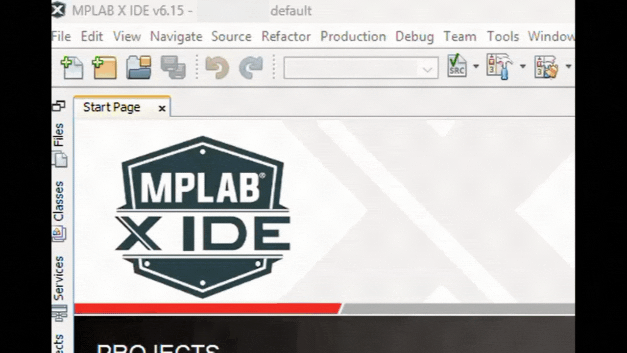
For Part 3, we’re going to finish our discussion by going over the code, line-by-line, and how it works. We’re even going to go over some common errors when trying to connect the PICkit device to the MPLAB IPE. Here is where we’ll finish up the project as a whole. Near the end, we’ll test the circuit and hopefully have a working circuit. Before we get to all that, we first need to create a new project in the MPLAB X IDE, of which we’ll discuss next.
First Steps to Programming Your PIC
Creating a New Project in MPLAB X IDE
Before we begin programming our PIC microcontroller, we need to open up the MPLAB X IDE and create a new project. The following steps show you how:
- Open up MPLAB X IDE v6.15 by double-clicking on the desktop icon.
- To create a new project, click on the File drop-down menu on the taskbar at the top of the IDE, then click on New Project.
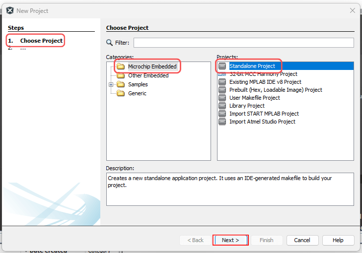
- Once you click on New Project in the File drop-down menu, a New Project window will open. Step 1 is Choose Project, as you can see in the left section of the window. Make sure that Microchip Embedded is highlighted under the Categories menu pane. Also, make sure that you click on the Standalone Project option under the Projects menu pane. Then, click Next.
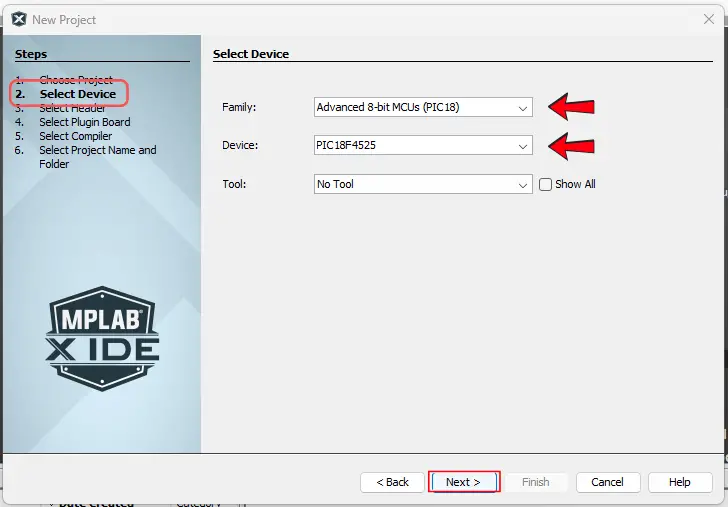
- Now, for step 2 in the Select Device section of the New Project window, click on the drop-down arrow of the Family selection. Since we’re using the PIC18F4525 microcontroller, we will make the choice for the Advanced 8-bit MCUs (PIC18). Next, click the drop-down arrow of the Device selection. You can either scroll down to the PIC18F4525 choice or type in “PIC18F4525” into the drop-down box itself. For now, leave No Tool under the drop-down menu for the Tool selection. Then, click Next.
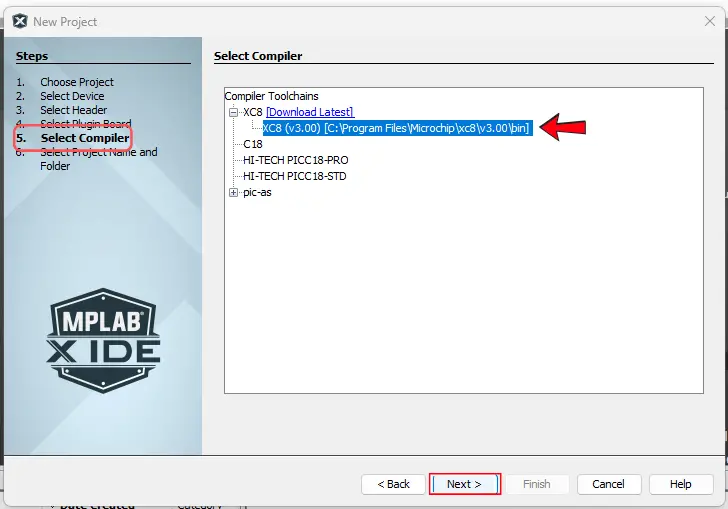
- Now we should be skipped down to step 5 to Select Compiler. I click on XC8 (v3.00), because that’s what I’m using. After choosing your compiler, click Next.
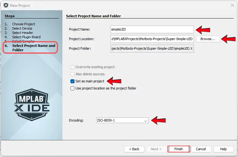
- Now we’re at step 6, the final step in the New Project window to Select Project Name and Folder. Under the Project Name box option, type in the name of the project. In this case, I’ve called our project “simpleLED”. You can leave the Project Location or choose where you want this project to be saved on your computer – same goes for the Project Folder option. Make sure that you know where your project will be saved. Leave the Set as main project box checked. Leave the Encoding option as ISO-8859-1. To finish, click Finish.
Creating a New File in MPLAB X IDE
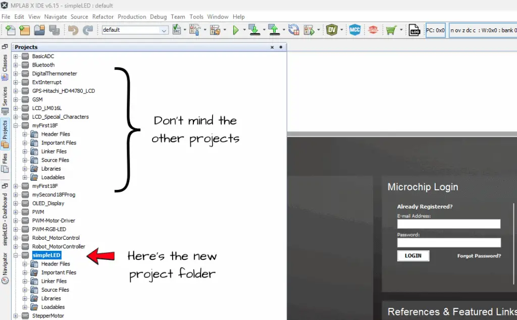
Once we create a new project, we need to create a new file to write our code in. After we clicked Finish in step 6 of creating a New Project, we should see our simpleLED project folder in the side pane of the Projects tab in the MPLAB X IDE.
To create a new file, right-click on the Source Files sub-folder of the simpleLED project folder we just created. Once the pop-out menu appears, hover on New to allow for another side-menu to show, then click on the main.c option, as shown in the GIF image below:
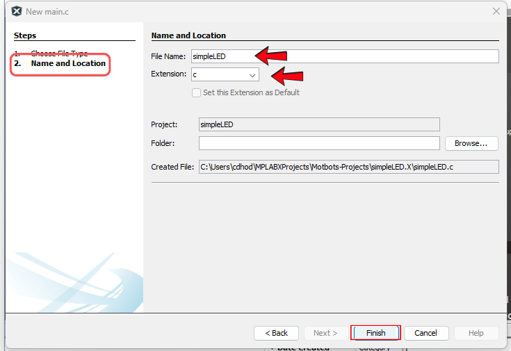
Now, we should see a New main.c window pop-up on our screen. We should be started at step 2 in the Name and Location section of the New main.c window. All we have to do now is to give our file a name in the box under File Name. I have named my file the same name as the project folder, simpleLED. Leave the Extension option as c. Then, click Finish.
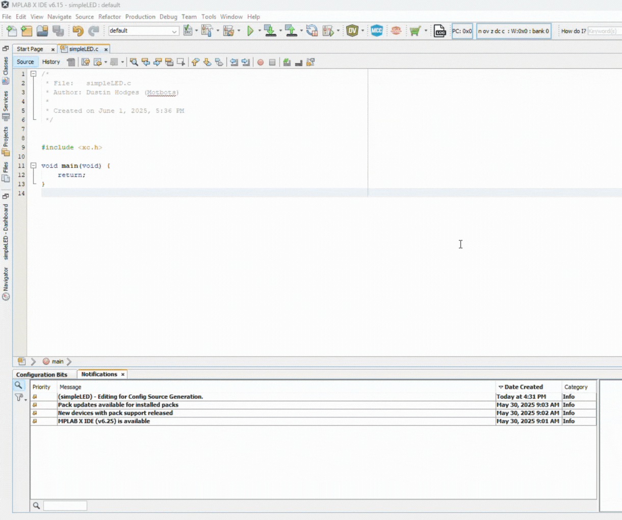
Now we have our file named simpleLED.c, that we’re going to use to write our C code and have saved it under the Source Files in our simpleLED project folder. The first thing well need to do though, in our code is to setup the configuration bits for the PIC microcontroller. We’ll do that next.
Configuration Bits
When programming a PIC microcontroller, one of the first things that you need to do is to set the configuration bits. Configuration bits in PIC microcontrollers are special settings stored in non-volatile memory that determine the fundamental operating modes and hardware features of the microcontroller.
Basically, what we need to do is to tell the PIC18F4525 how we intend to use some of its main variable attributes. The primary purpose of configuration bits is to customize the behavior of the microcontroller to meet the requirements of the specific application we intend to use the PIC for. One such attribute we intend to manipulate here, is for the clock signal of the PIC18F4525 microcontroller.
Clock Signal
One such configuration bit we need to set is the clock signal. The clock signal or source determines the oscillator type – whether that be internal, an external crystal oscillator, or an RC oscillator – and its frequency. This is a crucial step in configuring our PIC, and is essential for setting the clock speed of the microcontroller. What we’ll want to do for this project is to set the oscillator type to internal.
All instructions in the program and all other actions are synchronized to a clock signal. So, what we need to do is to tell the PIC which oscillator we intend to use. To do this, we write the correct data to the configuration registers in the PIC. This data determines how we are going to use the PIC.
How to Set the Configuration Bits in MPLAB X
The steps of setting up the configuration bits of a PIC microcontroller using Microchip’s MPLAB X software we installed on our computer are as follows:
- Click the Window drop-down menu on the taskbar at the top of the IDE.
- Under the Window drop-down menu, hover over the Target Memory Views option to expose another drop-down menu.
- Under the Target Memory Views drop-down menu, select the Configuration Bits option.
A new tab called Configuration Bits should have opened in the Window Group panel at the bottom of the IDE.
At this point, there are three main options we want to change:
- OSC to INTIO67
- Set the oscillator option (OSC) to use the internal oscillator block as the primary source and leave bits 6 and 7 on PORTA as normal input-output bits.
- WDT to OFF
- It is important to turn the watchdog timer off, because if nothing happens for a predefined period of time in a program, then the WDT will stop the program.
- LVP to OFF
- Turning the low-voltage programming off.
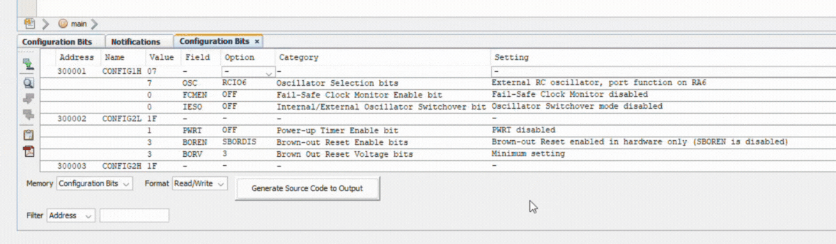
We’ll leave all other options as they are. Once we’ve made our changes, we’ll generate the source code to output, by clicking on the Generate the Source Code to Output button, as seen in the GIF image below:
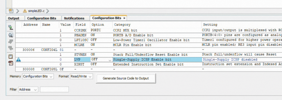
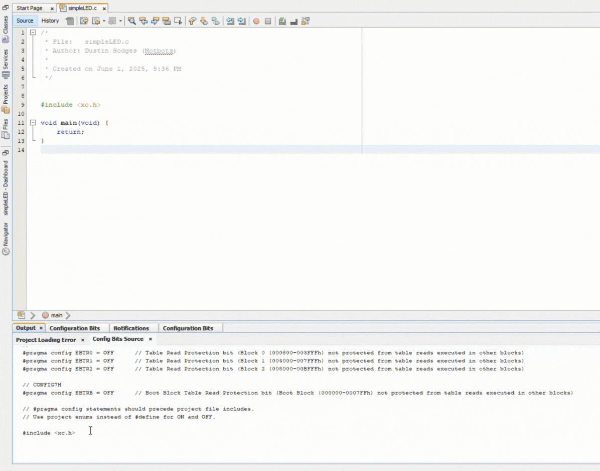
Poof! We have our generated source code with our configuration bits – all done for us! Now, we just need to copy it all, then paste it into our code, at the top, as shown in the GIF image below:
Now that we have the configuration bits done, let’s get on with the rest of the code! Next, we’ll include a header file and get into some SFRs.
#include<xc.h> and Special Function Registers (SFRs)
At the top of our code, after the configuration bits, the very first line of code should be to include the xc.h header file for use for later. This should have been added at the bottom with the configuration bits when we copied and pasted the generated source code. It should look like the following:
#include <xc.h>As per Microchip’s website, The xc.h header file allows code in the source file to access compiler-specific or device-specific features. We use the preprocessor #include to tell the compiler that we want to include a file or library in our code, and that file is within the xc.h header file.
The #include<xc.h> is important for us to use in our code to tell the compiler we want to use some labels to represent any addresses we will be using for this project.
The most important addresses we will use are what’s called SFRs, or special function registers, that we can use to control every aspect of the PIC with the ‘1s’ and ‘0s’ that they write to these control registers. Compilers understand ‘1s’ and ‘0s’ as binary input assembled in a sequence that forms bytes or bits of information as machine code. Humans understand labels in human written language.
- Compiler: Really wants to use the address of the registers.
- Human: Really wants to use labels to give the registers names instead of using the actual address number.
An example of a label we’ll use for the PIC18F4525 is the PORTA label. There are up to five ports available for this PIC: PORTA, PORTB, PORTC, PORTD, and PORTE.
The PORTs of a PIC act as the GPIOs or Genral Purpose Input/Output pins. The PORT register of a PIC reads the levels on the pins of the device. PORTA on the PIC18F4525 microcontroller is an 8-bit wide, bidirectional port – meaning its pins can be set as either for input or output. You can learn more about I/O PORTs, and PORTA in particular, for the PIC18F4525 MCU on page 91 of the datasheet.
Example Label: PORTA
- PORTA is an SFR at the address 0xF80 in the PIC18F4525.
- The compiler only needs the hexadecimal number “F80”.
- The “0x” prefix in the address 0xF80 stands for hexadecimal.
- We want to use the label “PORTA”.
- We have to tell the compiler that the label PORTA, and any other labels, represent the correct address of the SFRs.
- There’s a simple instruction that does this: EQU PORTA 0XF80
To help us do this, and save time, someone has written the EQUs for all the labels for all the SFRs we can use.
- To use these equates, we need to tell the compiler in our program to include them in our program by using the #include<xc.h> line in our program.
- This links together our own program and all the header files we tell the linker program in “include”, but we must tell the linker program to include them.
The Code
/******************************************************************************
*
* File: simpleLED.c
* Author: Dustin Hodges (Motbots)
* Microcontroller: PIC18F4525
* Date: 06/01/2025
*
* Project: A basic program to turn on and off an LED.
* Hardware: We are using the microcontroller to switch an LED
* ON and OFF. The following pins are used on the PIC18F4525:
*
* RA0 --> "ON" Switch (SW1)
* RA1 --> "OFF" Switch (SW2)
* RB0 --> LED (LED1)
*
* Last Updated on June 1, 2025, 8:53 PM
******************************************************************************/
// PIC18F4525 Configuration Bit Settings
// 'C' source line config statements
// CONFIG1H
#pragma config OSC = INTIO67 // Oscillator Selection bits (Internal oscillator block, port function on RA6 and RA7)
#pragma config FCMEN = OFF // Fail-Safe Clock Monitor Enable bit (Fail-Safe Clock Monitor disabled)
#pragma config IESO = OFF // Internal/External Oscillator Switchover bit (Oscillator Switchover mode disabled)
// CONFIG2L
#pragma config PWRT = OFF // Power-up Timer Enable bit (PWRT disabled)
#pragma config BOREN = SBORDIS // Brown-out Reset Enable bits (Brown-out Reset enabled in hardware only (SBOREN is disabled))
#pragma config BORV = 3 // Brown Out Reset Voltage bits (Minimum setting)
// CONFIG2H
#pragma config WDT = OFF // Watchdog Timer Enable bit (WDT disabled (control is placed on the SWDTEN bit))
#pragma config WDTPS = 32768 // Watchdog Timer Postscale Select bits (1:32768)
// CONFIG3H
#pragma config CCP2MX = PORTC // CCP2 MUX bit (CCP2 input/output is multiplexed with RC1)
#pragma config PBADEN = ON // PORTB A/D Enable bit (PORTB<4:0> pins are configured as analog input channels on Reset)
#pragma config LPT1OSC = OFF // Low-Power Timer1 Oscillator Enable bit (Timer1 configured for higher power operation)
#pragma config MCLRE = ON // MCLR Pin Enable bit (MCLR pin enabled; RE3 input pin disabled)
// CONFIG4L
#pragma config STVREN = ON // Stack Full/Underflow Reset Enable bit (Stack full/underflow will cause Reset)
#pragma config LVP = OFF // Single-Supply ICSP Enable bit (Single-Supply ICSP disabled)
#pragma config XINST = OFF // Extended Instruction Set Enable bit (Instruction set extension and Indexed Addressing mode disabled (Legacy mode))
// CONFIG5L
#pragma config CP0 = OFF // Code Protection bit (Block 0 (000800-003FFFh) not code-protected)
#pragma config CP1 = OFF // Code Protection bit (Block 1 (004000-007FFFh) not code-protected)
#pragma config CP2 = OFF // Code Protection bit (Block 2 (008000-00BFFFh) not code-protected)
// CONFIG5H
#pragma config CPB = OFF // Boot Block Code Protection bit (Boot block (000000-0007FFh) not code-protected)
#pragma config CPD = OFF // Data EEPROM Code Protection bit (Data EEPROM not code-protected)
// CONFIG6L
#pragma config WRT0 = OFF // Write Protection bit (Block 0 (000800-003FFFh) not write-protected)
#pragma config WRT1 = OFF // Write Protection bit (Block 1 (004000-007FFFh) not write-protected)
#pragma config WRT2 = OFF // Write Protection bit (Block 2 (008000-00BFFFh) not write-protected)
// CONFIG6H
#pragma config WRTC = OFF // Configuration Register Write Protection bit (Configuration registers (300000-3000FFh) not write-protected)
#pragma config WRTB = OFF // Boot Block Write Protection bit (Boot Block (000000-0007FFh) not write-protected)
#pragma config WRTD = OFF // Data EEPROM Write Protection bit (Data EEPROM not write-protected)
// CONFIG7L
#pragma config EBTR0 = OFF // Table Read Protection bit (Block 0 (000800-003FFFh) not protected from table reads executed in other blocks)
#pragma config EBTR1 = OFF // Table Read Protection bit (Block 1 (004000-007FFFh) not protected from table reads executed in other blocks)
#pragma config EBTR2 = OFF // Table Read Protection bit (Block 2 (008000-00BFFFh) not protected from table reads executed in other blocks)
// CONFIG7H
#pragma config EBTRB = OFF // Boot Block Table Read Protection bit (Boot Block (000000-0007FFh) not protected from table reads executed in other blocks)
// #pragma config statements should precede project file includes.
// Use project enums instead of #define for ON and OFF.
#include <xc.h>
void main(void) {
// This is where the micro goes to find the first instruction of the program
//////////////////////////////
// MCU I/O initialization
//////////////////////////////
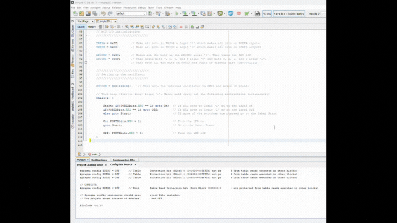
TRISA = 0xFF; // Make all bits in TRISA a logic '1' which makes all bits on PORTA inputs
TRISB = 0x00; // Make all bits in TRISB a logic '0' which makes all bits on PORTB outputs
ADCON0 = 0x00; // Makes all the bits in the ADCON0 logic '0'. This turns the ADC off
ADCON1 = 0x0F; // This makes bits 7, 6, 5, and 4 logic '0' and bits 3, 2, 1, and 0 logic '1'.
// This sets all the bits on PORTA and PORTB as digital bits (0b00001111)
//////////////////////////////
// Setting up the oscillator
//////////////////////////////
OSCCON = 0b01110100; // This sets the internal oscillator to 8MHz and makes it stable
// Test loop (forever loop) logic '1'. Micro will carry out the following instructions continuously)
while(1) {
Start: if(PORTAbits.RA0 == 1) goto On; // If RA0 goes to logic '1' go to the label On
if(PORTAbits.RA1 == 1) goto Off; // If RA1 goes to logic '1' go to the label Off
else goto Start; // If none of the switches are pressed go to the label Start
On: PORTBbits.RB0 = 1; // Turn the LED on
goto Start; // Go to the label Start
Off: PORTBbits.RB0 = 0; // Turn the LED off
}
}
The Code Explained
If you haven’t done so already, I highly suggest that you check out What We Need to Know in C from Part 1 of this series. There, we discussed – in detail – the main function, the while loop, the if-else statement, the goto statement and labels in C, and more on the preprocessor #include.
Since we’ve already gone over the configuration bits and the #include preprocessor we added in our code, we’ll go ahead and jump down to line 80, and discuss the main function. The comments at the top of the code are there for informational purposes about the code and its author. It’s good practice to write such comments at the top of any code you write – it informs all of what the code is for, who wrote it, and provides other key information as well.
The Opening of the Main Function
void main(void) {Line 80 marks the beginning of the main function. Please refer to Main Function from Part 1, to understand what the main function’s purpose is within C code.
TRISA and TRISB
TRISA = 0xFF;       // Make all bits in TRISA a logic '1' which makes all bits on PORTA inputs
TRISB = 0x00; // Make all bits in TRISB a logic '0' which makes all bits on PORTB outputsWe are wanting to use ports on the PIC to communicate with the outside world. For this project we are going to use PORTA as an input port, and PORTB as an output port. But how do we get the PIC to know that’s what we want to do?
The PIC has no idea which way we want to use the PORTs!
We learned from earlier that each PORT can be either an input or an output, and that each PORT on the PIC18F4525 has 8 bits. We also learned that PICs may have several ports that can be used to communicate to the outside world – all PICs have at least two PORTs, but the PIC18F4525 has five PORTs.
We’re just going to use two PORTs for this project. We will need to tell the PIC how we want to use those PORTs and their bits. To do this, there are some SFRs called TRIS which allow this to be done.
- There is a TRIS for each PORT.
- Each TRIS has the same number of bits as each PORT.
- The particular bit of each TRIS maps onto the same bit in the corresponding PORT.
- The bits of the TRIS can control the corresponding bits of the PORT as to whether or not the bit in the PORT is an input or an output.
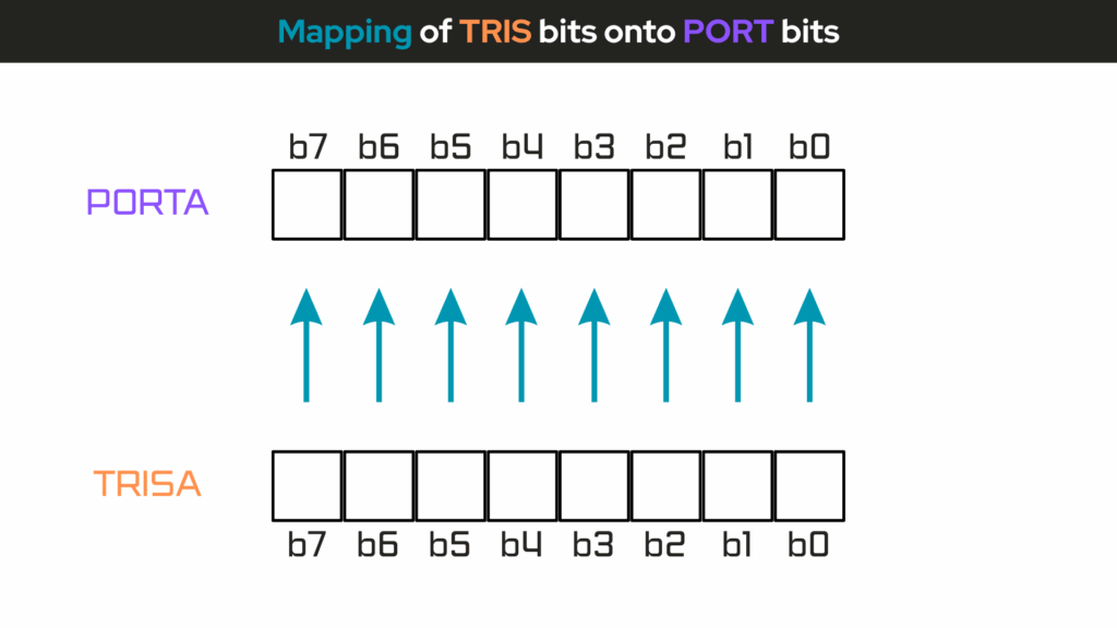
- If the bit in the TRIS is a logic ‘1’, then the bit in the PORT is an input.
- If the bit in the TRIS is a logic ‘0’, then the bit in the PORT is an output.
So, in our code we are wanting to tell the PIC that we want to make all the bits in TRISA a logic ‘1’, because this makes all the bits on PORTA inputs – TRISA bits correspond to PORTA bits. We’ll be using pins 2 (RA0) and 3 (RA1) on PORTA for our ON and OFF switches – switches SW1 and SW2, respectively. So, the PIC will need to respond to those input signals coming from either of those switches.
We are also wanting to tell the PIC that we want to make all the bits in TRISB a logic ‘0’, because this makes all the bits on PORTB outputs – TRISB bits correspond to PORTB bits. We’ll be using pin 33 (RB0) on PORTB for the LED. So, the PIC will need to respond by sending an output signal to turn the LED on or off, based on the input signal coming in from either of the switches on PORTA.
TRISA = 0xFF, where “0xFF” is a hexadecimal number representing the the binary number ‘11111111’. We’re wanting to make all the bits on PORTA inputs.
TRISB = 0x00, where “0x00” is a hexadecimal number representing the binary number ‘00000000’. We’re wanting to make all the bits on PORTB outputs.
| Hexadecimal | Binary |
| FF | 11111111 |
| 00 | 00000000 |
If you need to know the hexadecimal-to-binary conversion, check out the Getting Familiar With the Hexadecimal Number System in Part 1 of this project.
The ADC (Analog-to-Digital Converter)
ADC stands for Analog-to-Digital Converter, a peripheral in a microcontroller that converts an analog signal – like a voltage – into a digital value that the microcontroller can process.
Most PICs have an ADC that allows them to interface with sensors and other analog devices.
- This will be assigned to one of the PORTs
- This means that the inputs to the bits on that PORT could be analog or digital
- We must tell the PIC which we want the inputs to be: analog or digital
The ADC operation on PIC microcontrollers is controlled primarily through the ADCON (A/D Control) registers. Depending on the PIC family, there are typically two ADCON registers: ADCON0 and ADCON1. These registers configure the ADC module and control its behavior.
For the PIC18F4525:
- PORTA is assigned to the ADC and some of PORTB.
- The PIC18F4525 has 13 analog channels.
- This means that the bits on PORTA, and some of PORTB, could be analog or digital.
- The default setting is that they are all analog.
The principle behind the ADC is that there is just one ADC circuit inside the PIC which can be switched to any one of the 13 inputs that can have an analog input connected to it – a method called multiplexing – where 1 ADC serves 13 possible analog inputs. The ADC will then create a binary number system that represents the actual voltage applied to the input.
You can check our our discussion on binary-to-decimal conversions from Part 1 of this project series, to understand a bit more about the binary number system, if you’d like.
The ADC used in the PIC18F4525 is a 10-bit ADC (see pg. 1 – PIC18F4525 datasheet) which gives the programmer a possible resolution of:
\begin{equation}
\text{Resolution} = \frac{\text{Range}}{2^{n}}
\end{equation}
So, the ADC resolution is given by this formula:
\begin{equation}
\text{Resolution} = \frac{V_{REF+} – V_{REF-}}{2^{n}}
\end{equation}
Where:
- VREF+ is the positive voltage reference (usually tied to VDD, e.g., 5V)
- VREF- is the negative voltage reference (usually tied to VSS or GND, 0V)
- n is the number of ADC bits (10 bits for the PIC18F4525)
- 2n = 1024 steps (where n = 10, for 10-bit ADC)
The range and resolution, then becomes:
\begin{equation}
\text{Range} = V_{REF+} – V_{REF-} = 5V – 0V = 5V
\end{equation}
\begin{equation}
\text{Resolution} = \frac{(5V)}{2^{10}} = \frac{(5V)}{1024} = \boxed{4.88mV}
\end{equation}
The resolution is the smallest value that the ADC can recognize. This little digress into the discussion of the resolution tells us that if we wanted to enable the bits of the control registers of the PIC18F4525 to be analog, then the smallest value that the ADC could recognize would be 4.88 millivolts. This would mean that within the range of 0 to 5V, the ADC would only be able to “see” values within this range at 4.88mV increments. But, in our case, we don’t want to enable the control registers to be analog, we want them to be digital.

Recall that the ADC used in the PIC18F4525 is a 10-bit ADC. We want to use all 10 bits, but the PIC18F4525 is an 8-bit microntroller!
The ADC is controlled by three control registers:
- ADCON0: this register is primarily responsible for enabling the ADC and for which bit or channel the ADC is connected to.
- ADCON1: this register configures the voltage reference (e.g. VDD, VSS, or external) and the function to decide if the bit on the port is analog or digital.
- ADCON2: controls the timing of the ADC.
If we don’t want to use the ADC, and we want all the bits to PORTA to be digital, then we should turn off the ADC and make all bits on PORTA and PORTB to be digital.
Looking at the PIC18F4525 datasheet on pg. 223, for ADCON0, and pg. 224, for ADCON1, we make all bits of the ADCON0 register to be logic ‘0’. This will set b0 (bit 0) to a logic ‘0’ and turn the ADC off:
ADCON0:
- bit 7-6: Read as ‘0’
- bit 5-2: 0000 = Channel 0 (AN0)
- bit 1: 0 = A/D idle
- bit 0: 0 = A/D Converter module is disabled (turned off)
Bits 3, 2, 1, and 0 of the ADCON1 register determines if the bits on PORTA and PORTB are analog or digital bits:
ADCON1:
- bit 7-6: Read as ‘0’
- bit 5: 0 = VSS (Voltage reference configuration bit: VREF- source)
- bit 4: 0 = VDD (Voltage reference configuration bit: VREF+ source)
- bit 3-0: 1111 makes all the inputs to be digital
The following instructions in code will set the ADC up as we want:
ADCON0 = 0x00; // Makes all the bits in the ADCON0 logic '0'. This turns the ADC off
ADCON1 = 0x0F; // This makes bits 7, 6, 5, and 4 logic '0' and bits 3, 2, 1, and 0 logic '1'.
// This sets all the bits on PORTA and PORTB as digital bits (0b00001111)The combination of the following four instructions, from lines 88 to 89, and from lines 91 to 92 in code, will set the two ports as we want them:
TRISA = 0xFF;       // Make all bits in TRISA a logic '1' which makes all bits on PORTA inputs
TRISB = 0x00;       // Make all bits in TRISB a logic '0' which makes all bits on PORTB outputs
ADCON0 = 0x00;      // Makes all the bits in the ADCON0 logic '0'. This turns the ADC off
ADCON1 = 0x0F;      // This makes bits 7, 6, 5, and 4 logic '0' and bits 3, 2, 1, and 0 logic '1'.
// This sets all the bits on PORTA and PORTB as digital bits (0b00001111)Setting Up the Oscillator (OSCCON)
Previously, we have used the configuration words to tell the PIC we want to use the internal oscillator block as the primary oscillator source – INTIO67.
It is the bits in the OSCCON, OSCillator CONtrol register, that controls the internal oscillator block.
There are eight possible oscillator frequencies we can use and it is bits b6, b5, and b4 which control the settings.
- We want to set the oscillator to 8MHz.
- We want to make the frequency stable.
- We need to tell the PIC where it will get the signal for the system clock.
There are three possible options as controlled by bits b1 and b0 of this register.
Looking at pg. 30, of the PIC18F4525 datasheet:
OSCCON:
- bit 7: 0 = Device enters Sleep mode on SLEEP instruction
- bit 6-4: 111 = 8MHz (INTOSC drives clock directly)
- bit 3: 0 = Oscillator Start-up Timer (OST) time-out is running; primary oscillator is not ready.
- bit 2: 1 = INTOSC frequency stable
- bit 1-0: 00 = Primary oscillator
Bit 7 of the OSCCON register is the IDLEN bit which is used for sleep mode. We will not use this mode for now. Set this bit to a logic ‘0’.
Bit 3 is actually a signal from the microcontroller to the programmer so that this too can be set to a logic ‘0’.
This means that the eight bits in the OSCCON register can be set as follows:
OSCCON = 0b01110100; // This sets the internal oscillator to 8MHz and makes it stableThe Test Loop (While Loop)
We use this while loop at the end of our program to contain what we want our program to continuously loop through or test for. In this case, we want the PIC to continuously test to see if a user has pressed any of the buttons on our super simple LED switch circuit.
From lines 104 to 111, we use the goto statement and labels to directly go to a certain point in the code, like to Start, On, or Off – based on the situation of the circuit:
// Test loop (forever loop) logic '1'. Micro will carry out the following instructions continuously)
while(1) {

    Start: if(PORTAbits.RA0 == 1) goto On;  // If RA0 goes to logic '1' go to the label On
    if(PORTAbits.RA1 == 1) goto Off;        // If RA1 goes to logic '1' go to the label Off
    else goto Start;                        // If none of the switches are pressed go to the label Start

    On: PORTBbits.RB0 = 1;                  // Turn the LED on
    goto Start;                             // Go to the label Start

    Off: PORTBbits.RB0 = 0;                 // Turn the LED off
}Placing the PIC18F4525 MCU Into the Programmer Seat Adapter
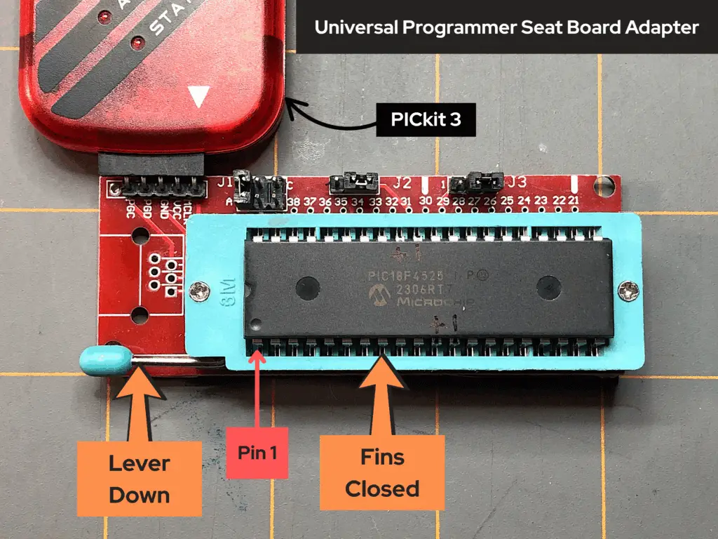
Before we connect the Universal Programmer Seat Board Adapter to the PICkit 3 programmer, and before we connect the PICkit to our computer, we want to place the PIC18F4525 microcontroller in the Programmer Seat Board Adapter. To do this, we must first remove the PIC18F4525 micrcontroller from the breadboard.
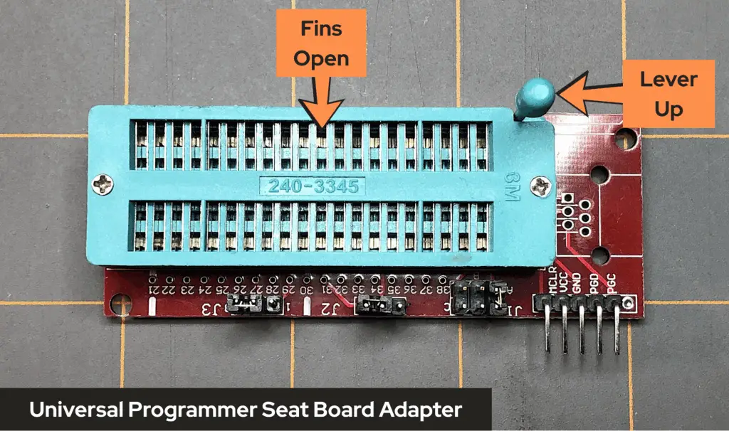
Before attempting to place the PIC’s pins into the Universal Programmer Seat Board Adapter, make sure that the handle to control the clamping fins of the Programmer Seat Board Adapter is in the up position. Doing so ensures that the clamping fins of the Programmer Seat Board Adapter are open and ready to accept the pins of the PIC microcontroller.
Once, the PIC has been removed from the breadboard, place its pins into the Programmer Seat Board Adapter, making sure that you orient the PIC to where its pin 1 reference dimple is facing next to the clamp handle of the Universal Programmer Seat Board Adapter, as shown in the image below:
Programmer Adapter Jumper Wires
Now that we have the PIC placed into the Universal Programmer Seat Board Adapter, we must configure the jumper wires of the Programmer Seat Board Adapter for the 40-pin PIC. To do this, we’ll need to refer to the labeling on the bottom-side of the adapter:
- First, take a look at the top-side of the Universal Programmer Seat Board Adapter and notice that there are three sets of pins on the right-side of the board. One set of 6 pins are labeled J1, one set of 3 pins labeled J2, and another set of 3 pins labeled J3.

- If we flip over the Universal Programmer Seat Board Adapter, there should be some labeling to instruct us as to how to position the jumper wires on each of the labeled sets of pins. We’re using a PIC18F4525 microcontroller for this project, so we’ll need to refer to the DIP40 instructions labeled on the back-side of the board adapter.
- First, we’ll need to make sure that J1 pins have the jumper wire on the pins labeled A.
- Next, we need to make sure that J2 pins have the jumper wire on the pins labled 2 and 3.
- Finally, we need to make sure that J3 pins have the jumper wire on the pins 2 and 3.
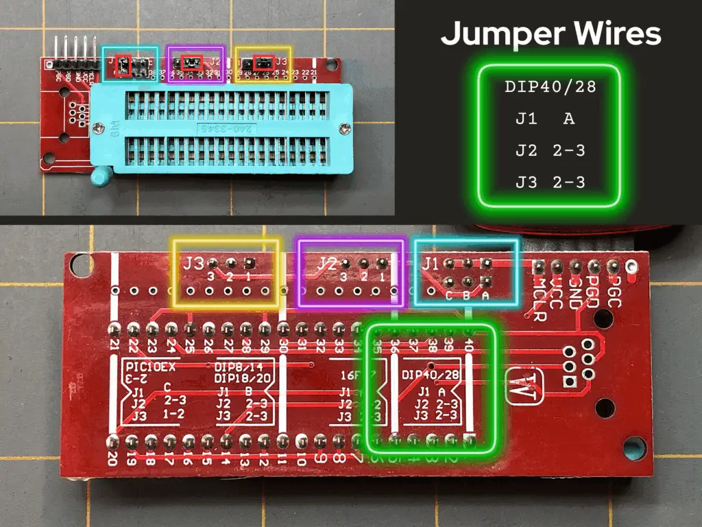
Configuring the jumper wires of the Universal Programmer Seat Board Adapter is an important step, so DON’T SKIT IT! Things won’t work right if you do. Next, let’s connect the PICkit 3 to our computer.
Connecting the PICkit 3 to the Computer
Now that we have our prototype circuit complete and our code ready to go, we need to compile the code and have it load to or PIC microntroller. We can compile the code without the PICkit connected to the computer, but we need it to be able to load the code’s hex file to the PIC. So, let’s go ahead and connect the PICkit 3 to our computer, first.
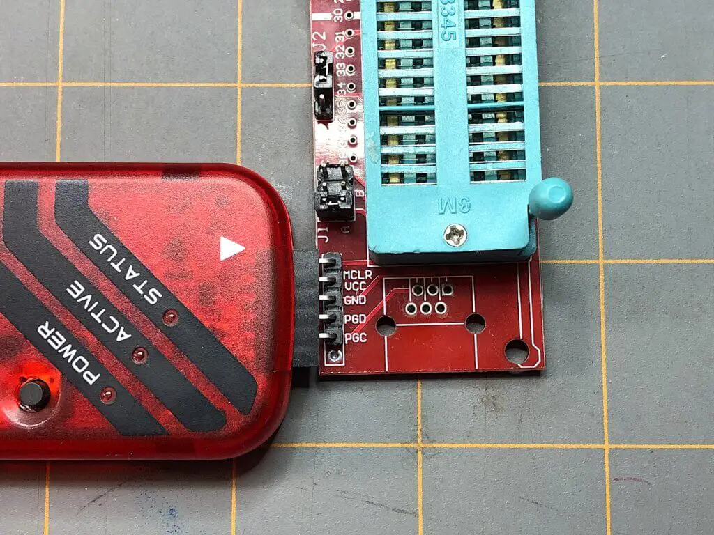
- Take the Universal Programmer Seat Board Adapter and connect its pins to the female DuPont connector at the bottom-end of the PICkit 3. Make sure that the MCLR pin is placed into the PICkit’s connector with the white triangular arrow pointed to it, as shown in the image below:
- Having the MPLAB IDE and our code up and ready to go on our computer, we can finally plug in the USB cable to the PICkit 3 and into our computer.
Once we’ve plugged the PICkit 3 into the computer using a USB cable, we’re now ready to compile our code to create the hex file we’ll need to upload to the PIC18F4525, from the PICkit 3 programmer.
Compiling Our Code
Now that we have the PICkit 3 ready to go and connected to our computer, let’s now go ahead and compile our code. To do this, we’ll perform the following steps:
- Looking at the taskbar at the top of the MPLAB X IDE window, click on Production.
- In the Production drop-down menu, click on Build Main Project (the hammer icon).
If your build was successful, and your code has compiled, we can now move on to loading the hex file that was saved in our project folder after compilation onto the PIC microcontroller using Microchip’s MPLAB X IPE software.
Connecting the PICkit Device to MPLAB IPE
Okay, we first wrote the code, then we compiled that code and converted it from a human readable language using C to binary encoded data-to-hexadecimal format – the hex file that the PIC can understand.
Now, we need to transfer or load that hex file into the PIC so that it can use that file to perform the instructions that we wrote that we want the PIC to perform. To do this, we need to use Microchip’s MPLAB X IPE and we need to connect our PICkit device to it:
- Make sure that your PICkit 3 is plugged into your computer with its USB cable.
- Open up MPLAB IPE v6.15 by double-clicking on the desktop icon.
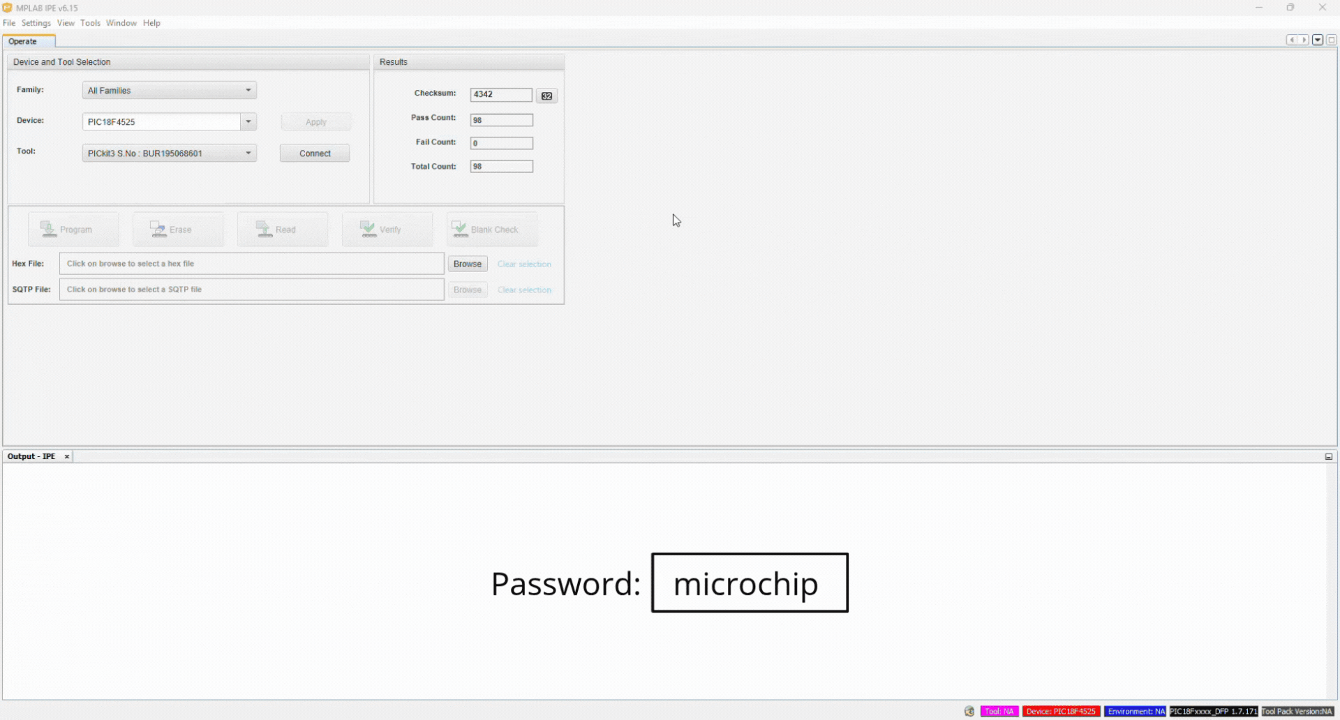
- Once the MPLAB IPE window is open, we need to login. Go to the top taskbar of the MPLAB IPE and click on the Settings option. In the drop-down menu, click on Advanced Mode. An Advanced Mode window should pop-up on your screen, prompting you to log in.
- To login to Advanced Mode, type in the password “microchip” in the Password box (all lower-case). Then, click on Log in.
- Now, within the Device and Tool Selection panel of the window under the Operate tab, click on the drop-down arrow under the Family option. Click on the Advanced 8-bit MCUs (PIC18) option (see image under step 7).
- Next, click on inside the drop-down arrow box under the Device option. Type “PIC18F4525” in the box, and choose this PIC by clicking on this option (see image under step 7).
- Now, click on the drop-down arrow under the Tool option. Click on your PICkit 3 device. In my case, mine is named “PICkit3 S.No : BUR195068601”. Then, click Connect.
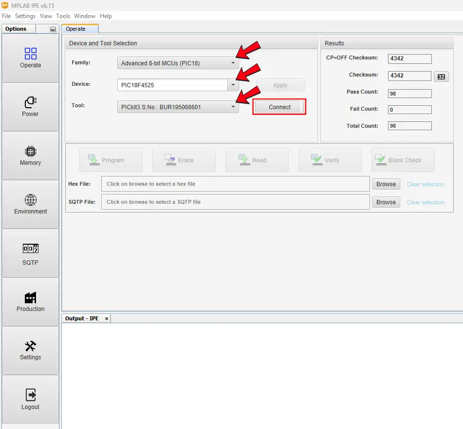
- After clicking on the Connect button, a prompt window should pop-up on your screen. It will begin with “CAUTION: Check that the device selected, blah, blah, blah…”. Just click OK.
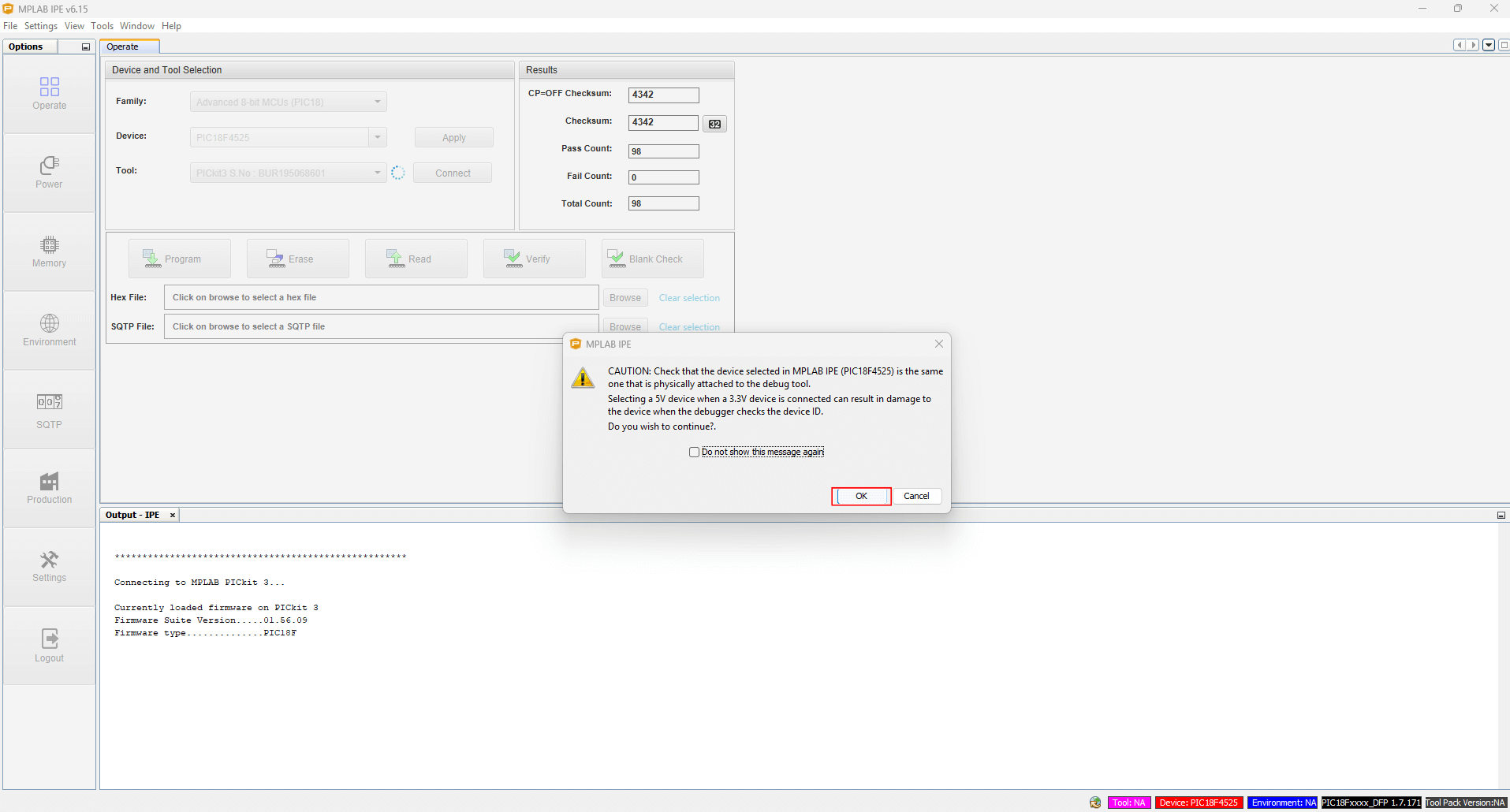
At this point, you may have received some sort of error message. In the proceeding, we will go over the three most common errors folks have when trying to get their PICkit device connected to the MPLAB IPE. If you’ve received any errors at this point, please see if any of the following solutions will help you.
If you do not have any error messages, then you may proceed to Loading a Hex File to a PIC using the PICkit 3 and MPLAB IPE.
Common Errors When Trying to Connect a PICkit Device to MPLAB IPE
Target Device Not Found Error
Once you logged into the MPLAB IPE and attempted to connect your PICkit 3 device, you may have received the following error message:
Target device was not found (could not detect target voltage VDD). You must connect to a target device to use PICkit 3.
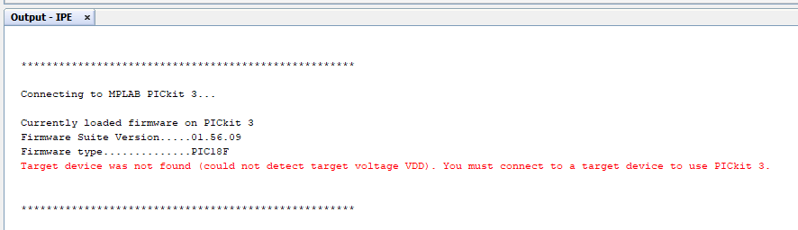
This is an easy fix! To fix this, all you need to do is the following:
- Looking to left-side panel of the MPLAB IPE window, we see several options in clickable boxes. One such option is the Power option with a power cord icon. Click on it (see GIF image below under step 4).
- Notice that a new tab in the MPLAB IPE window opens called Power. Within this tab is a Voltage options box with a checkbox option for Power target circuit from PICkit3. If this checkbox is not checked, go ahead and check the checkbox (see GIF image below under step 4). For now, we’ll leave the Voltage Level option as is, at 5.0.
- Go back to the Operate tab by either clicking on the Operate tab in the MPLAB IPE window, or press on the Operate box with the four small square pattern in the left-side pane.
- Make sure all the options we selected for the Device and Tools selection are the same as before in the previous steps, then click the Disconnect button next to the Tool selection.

- Next, click on the Connect button again, to connect the PICkit3 tool.
- Again, a prompt window should pop-up on your screen. It will begin with “CAUTION: Check that the device selected, blah, blah, blah…”. Just click OK.
NOTE: Once you perform the following steps, you may receive another error – one that states that “too much current has been drawn on VDD.” If you got that message, then proceed to the next heading titled Too Much Current Has Been Drawn on VDD Error, where we easily fix this.
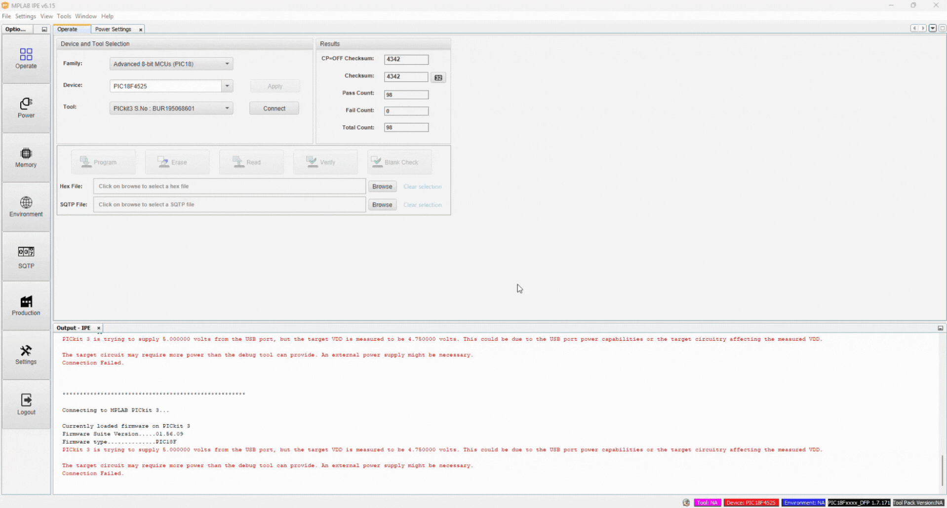
If you got some other error, like one that states something about the supply voltage and how the target VDD is measured to be 4.750000 volts, for example, then go to the heading PICkit 3 Target VDD Error, where we easily fix this.
Too Much Current Has Been Drawn on VDD Error
After attempting to connect your PICkit programmer to MPLAB IPE, you may have received the following error message:
Too much current has been drawn on VDD. Please disconnect your circuit, check the CLK and DATA lines for shorts and then reconnect.
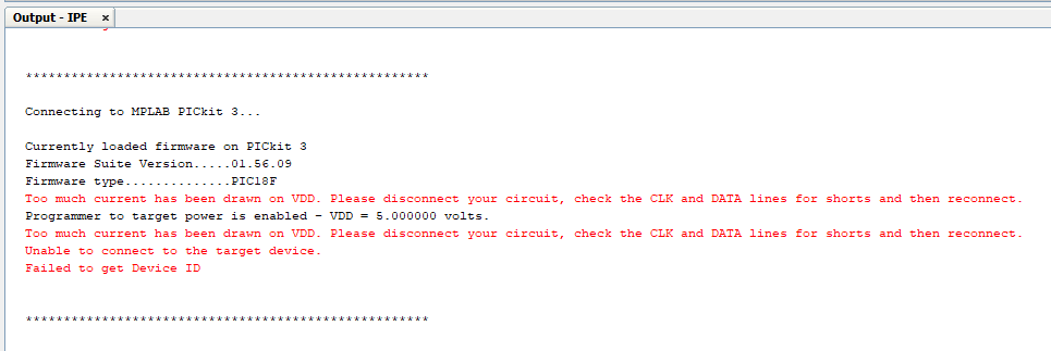
If you’ve received this error, there’s an easy way to fix it – at least in the sense that it worked for me. In any case, you can try what I did:
- Unplug your PICkit 3 programmer USB cable from the computer-side.
- Wait a few seconds, then plug your PICkit 3 programmer USB cable back into your computer.
- Make sure you’re at the Operate tab in the MPLAB IPE window.
- Make sure all the options we selected for the Device and Tools selection are the same as before in the previous steps, and that your PICkit device is showing in the Tool option.
- Next, click on the Connect button again, to connect the PICkit 3 tool.
- Again, a prompt window should pop-up on your screen. It will begin with “CAUTION: Check that the device selected, blah, blah, blah…”. Just click OK.
NOTE: Once, you do this you may now receive a new error message – one that states something about the “PICkit 3 trying to supply 5.000000 volts from the USB port, but the target VDD is measured to be 4.750000 volts”, or some other voltage value.
If you did receive such an error, then proceed on to the next heading titled PICKit 3 Target VDD Error, where we fix this issue too.
PICKit 3 Target VDD Error
If you received some sort of error message in the Output pane at the bottom the MPLAB IPE like the following:
PICkit 3 is trying to supply 5.000000 volts from the USB port, but the target VDD is measured to be 4.750000 volts. This could be due to the USB port power capabilities or the target circuitry affecting the measured VDD.
The target circuit may require more power than the debug tool can provide. An external power supply might be necessary.
Connection failed.
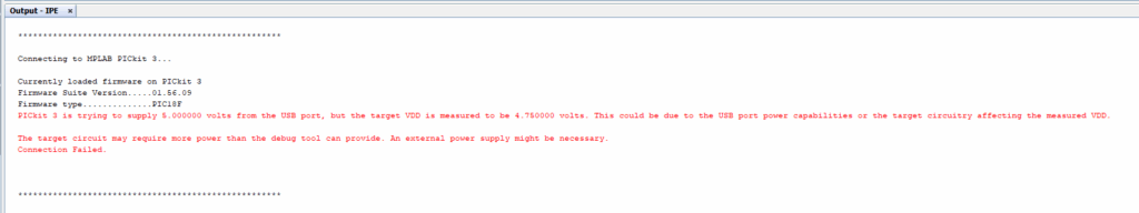
… then you’re probably frustrated at this point. Don’t worry though, because we can fix this too. To fix it, we can perform the following steps:
- Looking to left-side panel of the MPLAB IPE window, we see several options in clickable boxes. One such option is the Power option with the power cord icon. Click on it.
- In the Voltage options panel, keep the Power target circuit from PICkit3 box checked. Under the Voltage Level drop-down selection, choose 4.75, since our error mentioned that the target VDD is measured to be 4.750000 volts (see GIF image below).
- Now, referring back to the left-side panel on the MPLAB IPE window, click on the Operate box option or you can click on the Operate tab next to the Power Settings tab of the main panel.
- Click on the Connect button again, to connect the PICkit3 tool.
- Again, a prompt window should pop-up on your screen. It will begin with “CAUTION: Check that the device selected, blah, blah, blah…”. Just click OK.
Now, you should hopefully see something like “Target device PIC18F4525 found” in the Output pane at the bottom of the MPLAB IPE window. Your PICkit 3 is now connected! Woohoo!

Now that we finally got the PICkit device connected to the MPLAB IPE, and that they’re communicating with each other, now we’re able to load the hex file to the PIC microcontroller from the IPE, through the PICkit programmer, and onto our PIC. Let’s do that next.
Loading a Hex File to a PIC using the PICkit 3 and MPLAB IPE
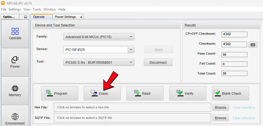
Before I import a hex file into MPLAB X IPE, I like to erase what may be on the PIC’s memory, first. To do this, click on the Erase box option in the panel below Device and Tool Selection under the Operate tab of the MPLAB IPE.
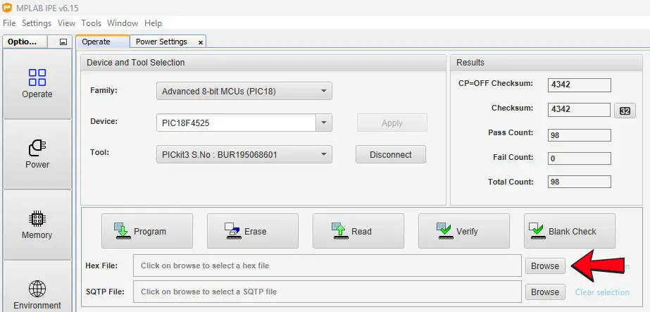
It’s time to import our hex file. To do this, perform the following steps:
- Click on the Browse button next to the Hex File option in the panel below Device and Tool Selection under the Operate tab of the MPLAB IPE.
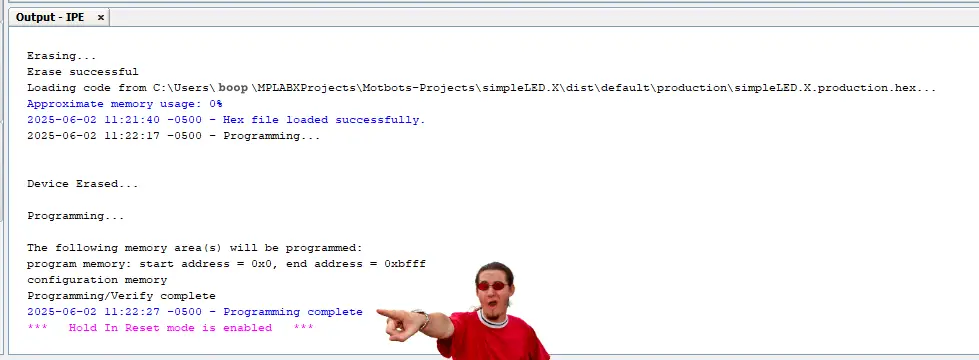
- Locate the hex file for this project on your computer. My hex file name is “simpleLED.X.production” and was located on my computer at the location “C:\Users\myComputerName\MPLABXProjects\simpleLED.X\dist\default\production”.
- Once you find the hex file for this project on your computer, select it. You should now see it show in the box of the Hex File option. You should also see a message say “Hex file loaded successfully” in the Output pane at the bottom the MPLAB IPE window.
- To load the hex file onto the PIC and program it, click on the Program button in the panel below Device and Tool Selection under the Operate tab of the MPLAB IPE.
If you performed the preceding steps properly, then you should receive a message “Programming complete” in the Output pane at the bottom the MPLAB IPE window.
Congratulations! You’ve done it! You’ve successfully programmed a PIC18F4525 microcontroller! Now all that’s left to do is to test it out on the prototype circuit. Let’s do that next!
Testing Our Prototype Circuit
After compiling and uploading the hex file for our code to the PIC microcontroller, we can go ahead and press the Disconnect button to disconnect the PICkit 3, logout of the MPLAB IPE, and unplug the USB cable for the PICkit 3 from the computer.
Next, we need to remove the PIC from the Universal Programmer Seat Board Adapter and replace the PIC back onto our breadboard prototype circuit. Make sure that you properly orient and align all the pins of the PIC back to the connections we made to it on the breadboard during the prototyping process.
To test the prototype circuit, all I had to do was to connect the +5V supply voltage from my benchtop power supply to the orange jumper wire connected to the positive power rail of my breadboard.
Then, I connected the negative supply of my benchtop power supply to the black jumper wire connected to the negative power rail of my breadboard.
Next, I turned on my benchtop power supply and observed what was happening on my prototype circuit on the breadboard.
- My red LED lit up.
- I pressed SW1 or the ON switch – of course, the LED was still lit, but I did this to initialize the Start point of the process we did in the code.
- Then, I pressed SW2 or the OFF switch and the LED turned off.
- Next, I pressed SW1 or the ON switch again, and the LED turned on.
- Finally, I pressed SW3 or the Reset button when the LED was on and noticed that the LED turned off when SW3 was pressed and back on when SW3 was released. Then, I repeated the previous steps again to make sure everything still functioned properly, and it did!
Success! The prototype circuit works! We did it!
Video: Super Simple LED Switch: Prototype Test (Updated Circuit)
Conclusion
Way to go! You’ve just programmed a bare-bones microcontroller to do things at your will! Isn’t it exciting to have accomplished such a feat?! Now that you know some of the basics of PIC programming, you can go on to creating bigger and more complex projects. FYI, the steps we took here for the PIC18F4525, are pretty much the same for any PIC microcontroller. So, if you want to use a different type, you can do so with ease!
I hope that you’ve found the information in this three part series and project useful, and hope that this content has been helpful for you. If it has, leave us a comment below. We’d love to hear from you. Help spread the word about Motbots, so that we may help others with similar interests as you in electronics and robotics.
We hope to proceed here, at Motbots, in developing more projects and ideas for you in the near future. Until then, keep at it and stay motivated!
Book Reference
A lot of thanks needs to be given to Hubert Henry Ward and his book titled C Programming for the PIC Microcontroller. The knowledge that he’s shared in his book has not only helped me in my understanding of PIC programming in C, but I’m sure in many others as well.
Mr. Ward’s book starts you in the basics of what you need to know, gradually building your understanding of C programming, PIC microcontrollers, and the MPLABX software. His book will walk you through, step-by-step, during the learning process and on to applying what you’ve learned by performing easy-to-follow projects, often providing pictures within the pages.
In his book, you’ll participate in PIC projects like an LED traffic light, creating a volt meter and use an LCD screen to view voltage outputs. You’ll even delve deeper into some more useful code using the C programming language for the PIC microcontroller.
I highly encourage you to check out Mr. Ward’s book, C Programming for the PIC Microcontroller, so that you too can learn about PIC programming using C.


Support Us
Help support Motbots, so that we may do more projects like this one, and share them with you! Thank you.