The Resistor Rundown: A Guide to Resistors
Introduction
Have you ever wondered how electricity enters an electronic device, moves through it, and ends up doing something useful?
You might have even asked yourself: Can I control that electricity? And if so, how is it done?
Those are excellent questions. To understand how electricity is controlled—or more specifically, how current in a circuit is controlled — we need to take a closer look at one of the most important components in electronics: the resistor.
What Is a Resistor?
A resistor is a passive electrical component with two terminals that provides resistance in a circuit. When a voltage source causes current to flow, the resistor opposes that flow as the electrical charges pass through it.
Resistors are made from materials that naturally resist the movement of electric charge. As current flows through a resistor, some electrical energy is converted into heat. Because of this behavior, the primary function of a resistor is to limit or regulate the flow of current in an electrical circuit.

Current Control: A Traffic Cop for Circuits
Current is allowed to pass through the resistor and the resistor does not actively do anything except restrict or limit the flow of current. You can think of a resistor as a sort of traffic cop, you know, for circuits. Its job is to just sit and wait for those speedy electrons until it can use its ability to control the flow of current or the traffic of electrons within the conductor highway.

Ohm’s Law: A Law All Resistors Abide By
Resistors follow a predictable rule known as Ohm’s Law. This law states that the current (I) flowing through a resistor is directly related to the voltage (V) across it and inversely related to the resistance (R). This relationship is expressed by the formula V = I × R.
Because of this relationship, resistors give us precise control over current and voltage within a circuit. By choosing resistors with appropriate resistance values, designers can limit current to safe levels, protect sensitive components, and ensure circuits operate as intended across a wide range of electronic applications.
Ohm’s Law
\begin{equation}
V = IR
\end{equation}

Uses of Resistors: Resistance Is Not Futile, It’s Necessary!
At first glance, a resistor may seem like it doesn’t do much more than just slow the flow of the traffic of electrons… I mean, the flow of current in a circuit, but resistors are a bit diverse in their capabilities.
They are very important components, and dare I say, ubiquitous in every electrical circuit in the wild. Resistance is not futile, it’s necessary!
Resistors are used in various applications within electronic circuits, including:
- Reducing Current Flow: They help control the amount of current passing through a circuit, which is crucial for protecting sensitive components, like LEDs or microchips, from excessive current.
- Adjusting Signal Levels: Resistors can modify the amplitude of signals, making them essential in audio and radio frequency applications.
- Voltage Division: They are used in voltage divider circuits to produce a specific voltage output from a higher voltage input.
- Biasing Active Elements: Resistors provide the necessary voltage and current conditions for active components like transistors to operate correctly.
- Terminating Transmission Lines: They help prevent signal reflections in transmission lines, ensuring signal integrity.

Resistor Color Coding: Band of Colors
Resistor color coding is a system used to indicate the resistance value and tolerance of resistors through colored bands printed on their bodies. This method is essential for quickly identifying resistor specifications without needing to look up part numbers or specifications.

If we take a moment and observe the resistor in the photo above, we can see that there are several bands of different colors on it. Now, if we take a gander at the resistor color code chart below, we can see that there are several colors listed:

Each color corresponds to a specific number, which is how you decode the bands. For instance:
- Black = 0
- Brown = 1
- Red = 2
- Orange = 3
- Yellow = 4
- Green = 5
- Blue = 6
- Violet = 7
- Gray = 8
- White = 9
The tolerance is also represented by colors, where gold and silver indicate specific tolerances (gold = ±5 percent, silver = ±10 percent). Understanding resistor color coding is crucial for anyone working with electronics, as it allows for quick identification and ensures that circuits are made using correct values.
How to Read a Resistor by Its Color Bands
Typically, resistors have four, five, or six color bands. Here’s a quick breakdown of how to read them:
- Four-Band Resistors: The first two bands represent significant digits, the third band is a multiplier, and the fourth band indicates tolerance. For example, if you see red, red, brown, and gold, it translates to 220 ohms with a tolerance of 5 percent.
- Five-Band Resistors: These add an extra significant digit. The first three bands are significant digits, the fourth is the multiplier, and the fifth is the tolerance. So, a resistor with bands of brown, black, black, black, and gold would represent 100 ohms with a 5 percent tolerance.
- Six-Band Resistors: These are often used for precision applications. They include the same information as five-band resistors but add a second tolerance band, which can provide even more detailed specifications.
There is an excellent resistor color code calculating tool on our website that allows you to find resistor values for four and five color band resistors by using drop-down boxes to choose colors for each band of a resistor. It’s awesome! Go check it out!


Two Examples of How to Read a Resistor’s Color Code
Let’s first start with a mental image of what the ordering of the color bands will tell us. In the following examples, we’ll be using resistors that have four bands of colors on them.
Since each of our resistors have four bands of colors on them, we’ll start by representing each of them with four empty lines to fill as we read each color’s associated number. We’ll do this one resistor at a time, so don’t worry. Before we start reading a resistor’s color bands, our four empty lines will be… well, empty.
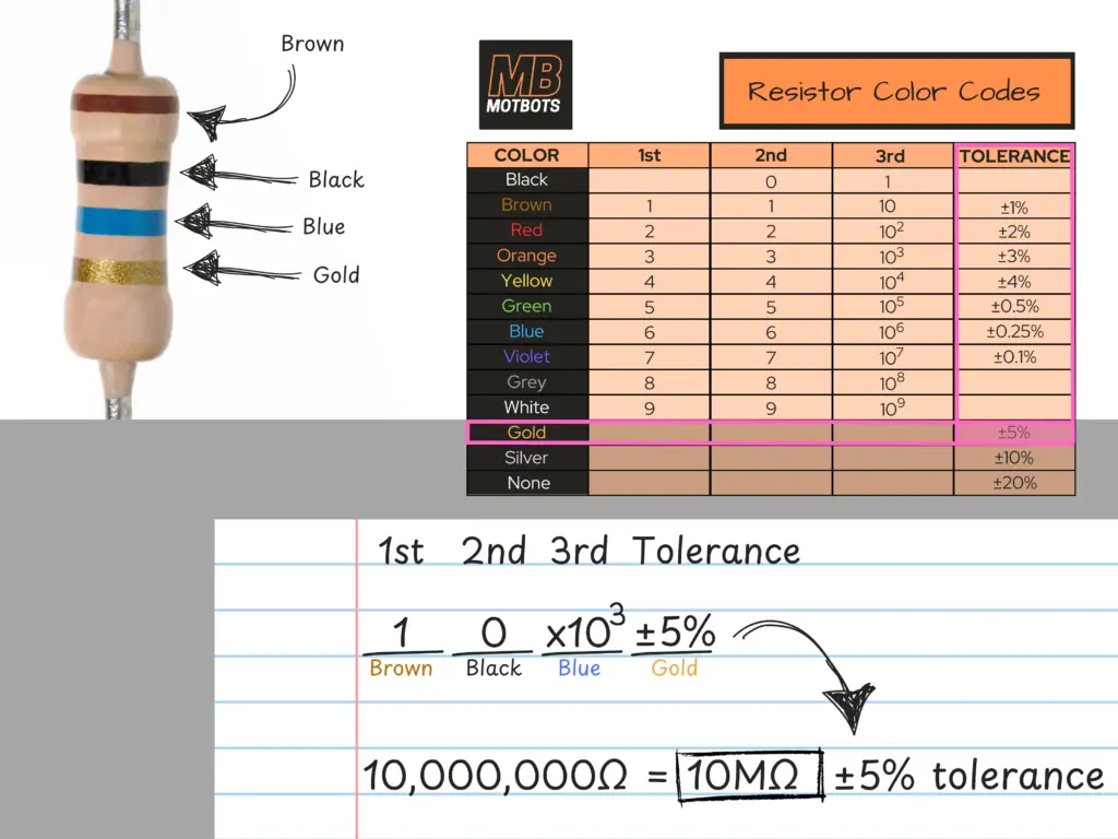
Brown-Black-Blue–Gold
Looking at the image of the example resistor below, we read its color bands starting at the farthest band away from the gold band, reading each stripe in succession. In this case, we see the color bands, in order, as Brown–Black–Blue, and then Gold.

Referring to the resistor color code chart, we start be reading the number associated with the first band (Brown) under the “1st” column. We see that the number 1 is in the “1st” column associated with the “COLOR” Brown. So, our first number read is 1, for the first color band, Brown.

Next, we continue to the second band on the resistor, it being Black. Reading the number associated with the second band (Black) under the “2nd” column, we see that the number 0 is in the “2nd” column associated with the “COLOR” Black. So, our second number read is 0, for the second color band, Black.

Continuing to the third band on the resistor, we see the color Blue. Reading the number associated with the third band (Blue) under the “3rd” column, we see a value in the “3rd” column associated with the “COLOR” Blue. That third value is 106, for the third color band, Blue — but wait, the third color band is the multiplier on a four-band resistor!
That means that we must take the first two numbers we found for the first and second color bands, and multiply the number they make by the multiplier of the third color band. That means we take the first and second color band numbers, 1 and 0, making it ten (10), and multiplying that number by the third color band’s number, the number 106 (10×106 = 10,000,000), making the value of the resistor a 10,000,000 ohm or 10 megaohm (10MΩ) resistor.

Finally, we read the forth, and last color band on the resistor, it being the color Gold. The forth band on a four-band resistor tells us the resistor’s tolerance value. Reading the number associated with the forth band (Gold) under the “TOLERANCE” column, we see that the value is ±5 percent. So, based on this value for the forth color band on our resistor (Gold), this tells us that our resistor has a tolerance value of ±5 percent.
So, our resistor has a value of 10MΩ, and a tolerance of ±5 percent. What this means is that if we were looking to obtain a resistor with a value of 10MΩ, say, then we’d look for a resistor with a four-band color code having its first three color bands being Brown-Black-Blue. If that resistor had its forth color band as Gold, then that would tell us that it has a tolerance of ±5 percent.
The ±5 percent tolerance means that if we were to multiply our resistor value (10MΩ) by the tolerance value (its percentage value of 5 percent), then add and subtract that figure from 10-million, we’d obtain a resistor value of either 9.5MΩ or 10.5MΩ.
So, based on a tolerance of ±5 percent, and assuming our resistor is a good one, then it should have a resistance value somewhere within the range of 9.5MΩ to 10.5MΩ, ideally being around the 10MΩ value we want, based on the color band value provided on the resistor’s body.
Video: How to Read a Resistor Color Code Chart
In the following video we’ll pretend that we found a resistor of unknown value. We want to identify the resistor’s value in ohms, and to do this we’ll use the band of colors printed on the resistor’s body.
Our example resistor has a color code banding of Blue–Grey–Brown and Gold. Here, we’ll quickly go over how to identify the resistor’s value in ohms using the color bands and a color code chart. A brief discussion will be given on the resistor’s tolerance value, as well.
Using a Resistor Color Code Calculator
If you’re not quite confident enough yet to read a color code chart – or you’re just to lazy to bother with one right now – an easy way to figure out what the ohm value is for a resistor is to use a resistor color code calculator. Just choose the number of color bands your resistor has, select the color of each band, then let the calculator do the work!
Interesting Facts and Unique Characteristics of Resistors
Here are some interesting facts and unique characteristics about resistors that many people might not know:
- Temperature Sensitivity: Resistors can change their resistance value with temperature fluctuations. This phenomenon is known as temperature coefficient. For instance, some resistors, like thermistors, are designed to change resistance significantly with temperature, making them useful for temperature sensing applications.
- Power Rating Matters: Every resistor has a power rating, which indicates how much power it can handle before it risks overheating and potentially failing. If too much current flows through a resistor, it can heat up and change its resistance or even get damaged. This is why it’s crucial to choose resistors with appropriate power ratings for your circuit.
- Types of Resistors: There are various types of resistors, each with unique properties. For example, carbon film resistors are known for their ruggedness and good tolerance, while metal film resistors are prized for their accuracy and low noise. Understanding these differences can help you select the right resistor for your specific application.
- Resistors in Series and Parallel: When resistors are connected in series, their total resistance increases, while in parallel, the total resistance decreases. This principle is essential for designing circuits that require specific resistance values.
- Ohm’s Law: Resistors play a crucial role in Ohm’s Law, which states that voltage (V) equals current (I) times resistance (R). This fundamental relationship is key to understanding how electrical circuits function.
- Noise Generation: Some resistors can generate electrical noise, which can interfere with sensitive electronic circuits. This is particularly true for carbon composition resistors. In contrast, metal film resistors tend to produce less noise, making them a better choice for high-precision applications.
- Historical Context: The concept of resistance and the use of resistors date back to the early days of electricity. The first resistors were made from carbon, and their development has evolved significantly over the years, leading to the diverse range of resistors we have today.
These lesser-known aspects of resistors highlight their complexity and importance in electronic circuits.
Resistors in Series
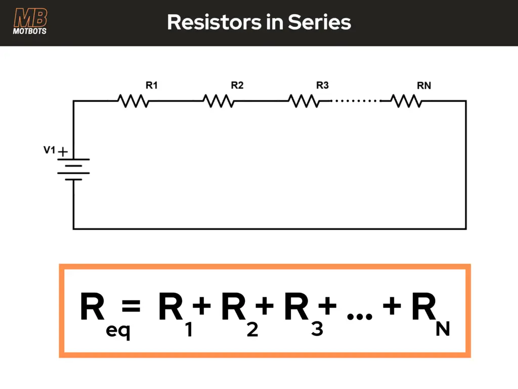
For resistors in series, the equivalent resistance (Req) is equal to the sum of each resistor in series with each other.
Problem: Let’s say that we’re doing a project that requires us to use a 2.7kΩ resistance value within its circuit somewhere. We go and search for a resistor for that particular value, but we can’t find one anywhere! Let’s say all we had were four resistors with the values 1kΩ, 1kΩ, 680Ω, and 15Ω. None of these will work! They’re all too low in value! What do we do now?!
Solution: Well, if we knew about how resistors work, we would know that if we were to place resistors in series, we could add their resistance values, therefore increasing the total resistance value where the resistors were to be placed in the circuit in series with each other. For the formula for resistors in series below, the Req will stand the equivalent resistance. So, if we needed a resistor value of 2.7kΩ or 2700Ω, we could take some resistors of smaller values that add up to 2700Ω, if we place them end-to-end or in series in the circuit. Let’s try the four resistors we have and see if we can make a 2700Ω resistor.
Resistors in series increases their total resistance:
\begin{equation}
R_{eq} = R_1 + R_2 + R_3 + R_4
\end{equation}
\begin{equation}
R_{eq} = 1kΩ + 1kΩ + 680Ω + 15Ω
\end{equation}
\begin{equation}
R_{eq} = 1000Ω + 1000Ω + 680Ω + 15Ω
\end{equation}
\begin{equation}
R_{eq} = \boxed{2695Ω}
\end{equation}
Hmm, we don’t quite have enough to make 2700Ω, but don’t fret! We’re only about 0.2 percent off the value we need, which is really good, therefore making it close enough! Good thing we had just the right amount of resistors we needed!
Resistors in Parallel
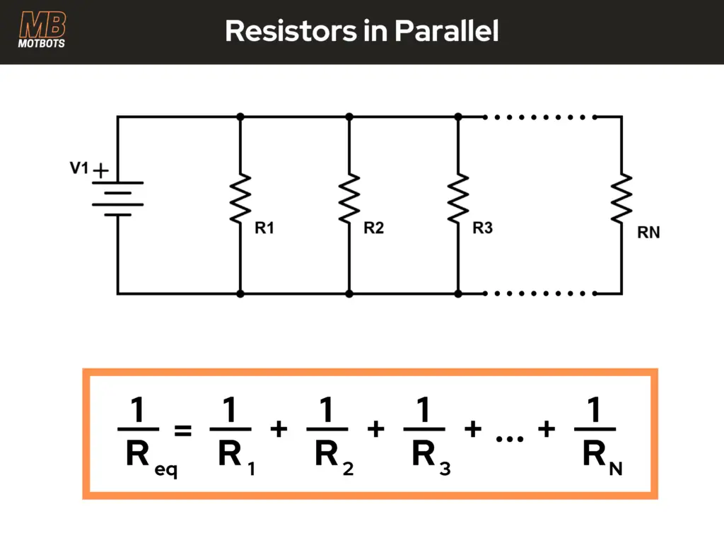
For resistors in parallel, the inverse of the equivalent resistance (Req) is equal to the sum of the inverses of each resistor in parallel with each other.
Problem: Let’s say we start the design phase of a new project and calculate that we need a resistance value of 63Ω somewhere in our circuit. Let’s also say that we looked behind our workbench and found three more resistors that had fallen on the floor. Each of their values are 100Ω, 200Ω, and 1kΩ. Not one of these resistors are valued anywhere near the value of 63Ω that we need. What do we do now?!
Solution: Again, if we knew about how resistors work, we would know that if we were to place resistors in parallel, we could reduce their total equivalent resistance. Meaning, that when resistors are placed in parallel with each other, their total resistance is lesser in value than any individual resistor value within that formation of parallel resistors.
That is the trick! You have to know that when you place resistors in parallel, the equivalent resistance of those resistors will be a value lower than the lowest resistor value in the parallel formation. For example, let’s say that you have three resistors in parallel, and the lowest valued resistor in parallel is 120Ω. That means that the equivalent resistance of those three resistors in parallel with each other, no matter what the other values are, will be a value lower than 120Ω.
So, if we’re needing an equivalent resistance value of 63Ω, we best make sure that the resistors we use in parallel with each other all be higher in value than 63Ω. All we have are values higher than 63Ω in our example, so we can try to place some of those higher valued resistors in parallel with each other that will give us the equivalent resistance we need.
Resistors in parallel decreases their total resistance:
Since we need to place resistors in parallel in our project, for this example, to make an equivalent resistance of 63Ω, we should start off with what we know. We know that we need an equivalent resistance value of 63Ω. We also know that we have on-hand one 100Ω resistor, one 200Ω resistor, and one 1kΩ resistor.
Let’s go ahead and see what happens if we use all three in parallel with each other what their equivalent resistance will be. We know that it will be a value below 100Ω, because that’s the smallest value of all our resistors. For the formula for resistors in parallel below, the Req will stand the equivalent resistance. Remember, we’re looking to get an Req value of around 63Ω. R1, R2, and R3 will represent the three resistors we have on-hand. Let’s hope and pray this works!
\begin{equation}
\frac{1}{R_{eq}} = \frac{1}{R_1} + \frac{1}{R_2} + \frac{1}{R_3}
\end{equation}
\begin{equation}
\frac{1}{R_{eq}} = \frac{1}{100Ω} + \frac{1}{200Ω} + \frac{1}{1000Ω}
\end{equation}
\begin{equation}
\frac{1}{R_{eq}} = \frac{10}{1000Ω} + \frac{5}{1000Ω} + \frac{1}{1000Ω}
\end{equation}
\begin{equation}
\frac{1}{R_{eq}} = \frac{16}{1000Ω}
\end{equation}
\begin{equation}
R_{eq} = \frac{1000Ω}{16}
\end{equation}
\begin{equation}
R_{eq} = \boxed{62.5Ω}
\end{equation}
WOW! How lucky are we?! We’ve basically just obtained an equivalent resistance value of 63Ω, or there about. Not bad for a days work, if I do say so myself.

Ohm’s Law Revisited: Finding the Resistance
Let’s say we want to make a simple circuit that is made only of a 9V battery, a red LED, and a resistor. We want the LED and resistor in series, connected across the battery terminals.
Let’s say that we have both the battery’s and the LED’s datasheets, and the LED’s datasheet says that we can give it 20mA or less.
Okay, so we know the limit of the current we can provide through our circuit. How much current does our 9V battery supply?
We look at the battery’s datasheet and it says that it has a battery capacity of 600mAh. 600mA through an LED is way more current that it can take before it blows! Hence, the reason why we need the resistor to limit the current from the battery through to the LED. But, what value of resistor should we use?
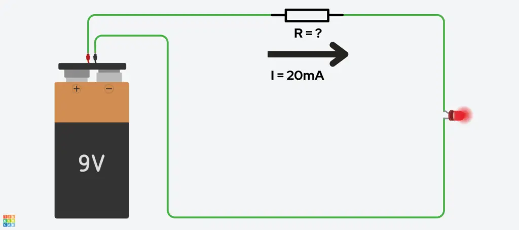
Dun, duh duh duhhh… Ohm’s Law to the rescue! We know the voltage provided to our circuit, it’s 9V. We know that our circuit only consists of a resistor and an LED in series, and Kirchhoff’s Voltage Law tells us the total voltage drop across the only two components in our circuit should be equal to 9V.
We know what our circuit current should be limited to, thanks to the LED’s datasheet — that was 20mA. So, we know the voltage, and we know what the current should be, so that means we can find the resistance!
\begin{equation}
V = IR
\end{equation}
\begin{equation}
R = \frac{V}{I} = \frac{9V}{20mA}
\end{equation}
\begin{equation}
R = \frac{9V}{20mA} = \frac{9V}{0.020A}
\end{equation}
\begin{equation}
R = \boxed{450Ω}
\end{equation}
So, Ohm’s Law is telling us that we need a resistor value of no less than 450Ω, to stay within the limit of 20mA being able to go through the circuit without damaging the LED. It’d be best to go a little higher than this figure, let’s say around 500Ω or so, that way we know we won’t be damaging our LED:
\begin{equation}
V = IR
\end{equation}
\begin{equation}
9V = I(500Ω)
\end{equation}
\begin{equation}
I = \frac{9V}{500Ω}
\end{equation}
\begin{equation}
I = 0.018A = \boxed{18mA}\checkmark
\end{equation}
\begin{equation}
18mA < 20mA
\end{equation}
That’s a little better. 18 milliamps is just enough below the LED’s current limit that we should be fine to not damage the LED at all.
Conclusion
In conclusion, resistors are fundamental components in electronic circuits, serving a variety of crucial roles such as controlling current flow, adjusting signal levels, and ensuring the proper functioning of active components.
Their color coding system allows for easy identification of resistance values and tolerances, while their unique characteristics, such as temperature sensitivity and power ratings, highlight the importance of selecting the right resistor for specific applications.
Understanding these aspects not only enhances our knowledge of electronics but also empowers us to design and troubleshoot circuits effectively. Whether you’re a hobbyist or a professional, grasping the intricacies of resistors is essential for working with electrical systems.