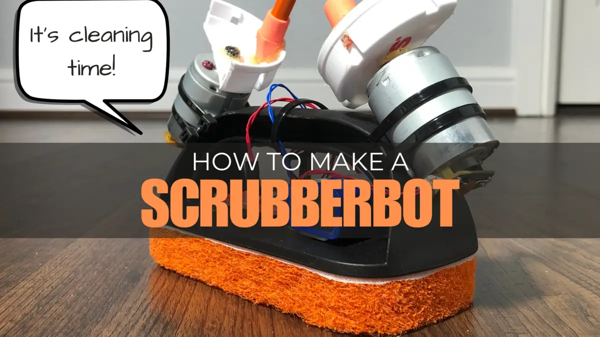
How to Make a Scrubberbot
| Project Name: | Scrubberbot |
| Project Description: | Learn how to make a scouring pad cleaning robot called Scrubberbot. |
| Project Difficulty: | Easy-to-Moderate |
| Project Note: | This project uses a soldering iron. Please use caution when using hot items. |
In this project, we’re going to make a battery powered scrubbing robot out of a scouring pad designed from a griddle cleaning kit I purchased online. This kind of project is easy if you’ve made projects similar to this before or moderate for the beginner and is a great way to learn how to use basic electronic components to make something useful and fun.
The Scrubberbot we’ll be making is a fun and easy project for beginners to get started in making robots. Not only is Scrubberbot a simple design, made from basic items and components, but it’ll help do chores around the house too!
Where The Design Came From
I came up with this design a couple of years ago when my then, 4 year old daughter and I made a similar robot design to Scrubberbot. We used one DC motor for its design and some of my daughter’s Lego® pieces to make a platform for its battery pack and motor. We slapped it all together with a few zip-ties and voilà! — A robot was cleaning our floors — sort of.
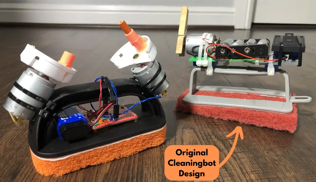
Let’s Be Methodical
I like to be very methodical about things, so we’ll go step-by-step — in detail — on the entire build of this project: the parts we’ll need, why we’re using them, how to connect them, how they work, and more! First, we’ll start with the following parts list:
Parts List
| Item | Quantity | Description |
| Scouring Pad with Handle | 1 | This will be the body of the robot. |
| 12V Brushed DC Motor | 2 | These two DC motors are what make our robot move. I salvaged my motors from old printers, but you can find motors at a place like Jameco.com. I’ve used them for years to order stuff from and have always enjoyed ordering from them. |
| Orange/Amber LED – 3mm Diffused | 1 | LED used as a power indicator. |
| 1kΩ Resistor | 1 | We use this to limit the current through our LED. |
| Slide Switch | 1 | This is our ON/OFF switch. |
| 1N4001 Rectifier Diode | 2 | These are used to suppress inductive voltage spikes by recirculating current through the motor. |
| 100nF Capacitor | 2 | These are used to reduce RF (Radio Frequency) and EM (Electromagnetic) interference caused by brush arcing between the brush and commutator of a DC motor. |
| 9V Battery | 1 | This is our power source. |
| 9V Battery Snap Connector | 1 | This makes connecting our battery to the circuit easier. |
| PCB Prototype Board 1.5×2.0×0.0625 in | 1 | We use this to solder our components together onto one board. |
| Spacers M2.5×5+5 mm | 4 | We use these, along with the screws and nuts, to create a space between our PCB board and the surface of the scouring brush handle base. |
| Screws M2.5×5 mm | 4 | We use these, along with the spacers and nuts, to create a space between our PCB board and the surface of the scouring brush handle base. |
| Nuts M2.5 mm | 4 | We use these, along with the spacers and screws, to create a space between our PCB board and the surface of the scouring brush handle base. |
| Medicine Bottle Lid | 1 | I used a medicine bottle lid, cut in half, to attach to the shaft of the motors to create an unbalanced rotation to cause vibrational movement from the motors. You can use whatever you’d like to create the same effect to make the robot move. |
| Hot-glue Gun with Hot-glue Stick | 1 each | I used hot-glue to help secure the medicine cap halves onto the motor shafts. |
| Zip-ties | 4 | We use these to secure the motors to the scouring brush handle. |
(Optional) Breadboard Prototyping Parts List
| Item | Quantity | Description |
| Solderless Breadboard | 1 | You can either use an 830 point or 400 point solderless breadboard for testing purposes. |
| Jumper Wires | Multiple Miscellaneous Sizes | We use these to make solderless connections to our components on the breadboard. |
Prototyping the Circuit

NOTE: Prototyping your circuit is optional, but recommended! Try it out!
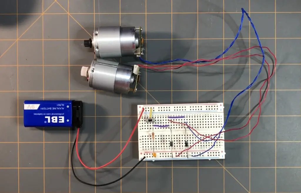
Before taking our parts and haphazardly soldering them together on our PCB prototype board, it’s good practice to first “dry-fit” our components — or temporarily put together our circuit on a breadboard.
If you need to — you may check out our Breadboard Basics page to understand the breadboard and how to use one.
You can skip this part if you’d like and go straight to the solderable PCB prototype board build for this project below.
Steps 0 – 9: How To Prototype The Scrubberbot Circuit
The following is a step-by-step process on how to put your components together on a breadboard to test to see if your circuit works before placing them permanently onto a solderable PCB prototype board.
- Soldering Capacitors Across Motor Terminals: Before we begin setting up our test circuit on the breadboard, we need to solder a 100nF (nano-farad) capacitor across the terminals of both of our DC motors. The reason why we want to place a capacitor across the terminals of our motor is briefly explained in the following:
- The brushes of a brushed DC motor make contact with its commutator and when the motor is operating it produces electrical noise or electromagnetic interference (EMI) due to the commutator and the switching of current within the motor. This EMI can interfere with other components within a circuit causing the entire system to perform unpredictably and unreliably.
- This EMI is shunted or absorbed through the capacitor. This action helps reduce the electrical noise that would affect other components within the circuit and helps stabilize the voltage across the motor — in turn creating a more predictable and reliable system.

- Breadboard Setup: First, take your breadboard and set it up for power — but DO NOT connect your battery or other power supply to it yet. I’ve shown you how to do this for either a 400-point or an 830-point breadboard. If you need to — you may check out our Breadboard Basics page to understand the breadboard and how to use one.
- 400 Point Breadboard: Connect the positive (red) terminal of the 9V battery snap connector to a positive (+) line of points on either outer edge of the breadboard — this will be our positive supply. Connect the negative (black) terminal of the 9V battery snap connector to a negative (-) line of points on the opposite outer edge of the breadboard — this will be our negative supply.
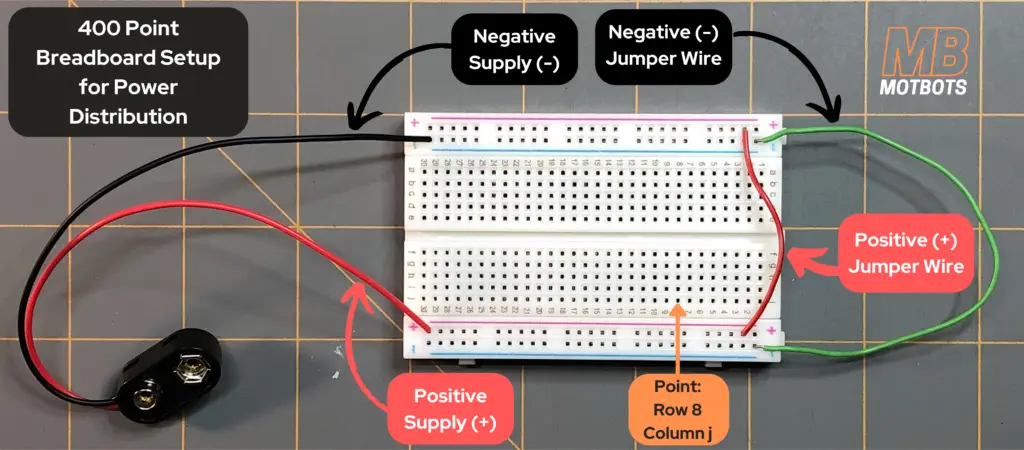
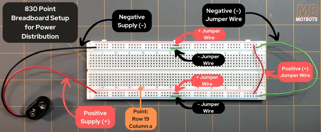
- 830 Point Breadboard: Connect the positive (red) terminal of the 9V battery snap connector to a positive (+) line of points on either outer edge of the breadboard — this will be our positive supply. Connect the negative (black) terminal of the 9V battery snap connector to a negative (-) line of points on the opposite outer edge of the breadboard — this will be our negative supply. We must also continue the connection of both positive (+) and negative (-) supplies of our breadboard down its other half on both sides of the board using jumper wires.
- Connecting The Switch: To be able to control our circuit we need to connect the switch. To do so in this setup, I’ve connected a jumper wire to the positive supply (yellow wire) inline with the center terminal of the slide switch. I placed the switch at points 26 through 28 on the breadboard — column b, as seen in the image below for step 2:

- Connecting The Resistor: We’re going to need a resistor to help reduce the current flowing through our LED in our circuit. I’ve placed one of the resistor terminals in point 26 of the breadboard — column e — inline with the terminal of the switch. I placed the other terminal of the resistor in point 26, column i — as seen in the image for step 3, below:

- Connecting The LED: The LED in our circuit is used as a visual indicator to let us know the circuit is ON when the slide switch is in its ON position. The anode (+) of the LED is placed at point 26, column j of the breadboard — the cathode (-) is in one of the negative supply points as seen in the image for step 4, below:

- At this point, if you’d like, you could connect your 9V battery to the battery snap connector and turn the switch ON to see if your LED lights up. If it does, great! If not, make sure you oriented your LED correctly. You can see how LEDs are properly oriented by visiting our post on LEDs here.
- Be sure to turn OFF the LED and disconnect the battery once you’re done testing before continuing.
- Connecting The First Diode: Next, we’re going to connect a diode in parallel with our resistor and LED. I connected a jumper wire (purple wire) from point 26, column d, of the breadboard to point 20, column d, to continue our path down the circuit. The cathode (-) terminal of the diode was placed in point 20, column e, of the breadboard — its anode (+) terminal placed in a point in the negative supply (ground), as seen in the image for step 5, below:

Why Are We Using A Diode Here In Our Circuit?
We’re using a diode here, because next in parallel with it will be our first DC motor with its attached parallel capacitor — the capacitor works to shunt or absorb current fluctuations from the motor when it’s running — creating a more steady voltage across the motor. The reasons why we use a diode in parallel with the motor is as follows:
- Notice the diode orientation in the image for step 5. The gray line on the diode represents the cathode (-) terminal of the diode. We’ve placed the diode with its cathode terminal facing opposite the negative supply of the breadboard and its anode (+) terminal into a point on the negative supply of the breadboard. If you need a refresher on diodes, check out this page here where we briefly discuss diodes and their orientations.
- We orient the diode in this backwards orientation (reverse biased) because we don’t want current to flow from the power supply (the 9V battery) and go through the diode straight to ground (negative supply). If the diode were forward biased it would cause a current loop through the diode and back around to the battery — skipping the branches of the circuit through the resistor and LED, as well as toward the motor — neither the LED or the motor would ever turn ON.
- The other reason why we reverse bias the diode is to allow the stored charge in the windings of the motor a path to flow to ground when the switch is turned OFF. Windings in a motor are essentially inductors and when a motor is ON its windings store electrical energy that could cause damage to components in a circuit and create an arc across a switch when the switch is moved to its OFF position.
- If there were no diode in our circuit, the LED would turn ON and the motor would turn ON. Everything would seem to be working normal — and it would be, to an extent, until you turn the switch to its OFF position.
- If there were no diode in our circuit, the reverse current would surge back to the switch when turned OFF, possibly causing an electrical discharge or arc across the switch. The capacitor would discharge its stored charge through the motor windings — creating a loop — and any leftover power would dissipate through the motor windings. This dissipation of power would be lost as heat.
- If we were to add a reverse biased diode in parallel with the motor and turn the switch ON, we’d see about the same results as we saw when the circuit had no diode.
- By adding a reverse biased diode in parallel with the motor — this provides a safe path for dissipation of stored energy when the switch is opened or turned to its OFF position.
- Connecting The First Motor: Now, it’s time to connect our first motor (motor 1) to the breadboard. I just removed about an 1/8 inch or so of the outer sheathing of the wires of the motor at the ends to expose the wire and twisted the wire to be able to insert them into the breadboard points. I placed one wire of the motor in point 20, column c, of the breadboard — the other wire of the motor was placed in a point at the negative supply rail of the breadboard, as shown in the image for step 6, below.

It does not matter which wire from the DC motor is placed at either point on the breadboard previously mentioned — the only difference observed is that the motor shaft will spin in the opposite direction if the wire ends are switched. This is based on preference — you choose whichever direction you want your motor to spin. Test this for yourself!
- Connecting The Second Diode: Now, we connect our second diode in parallel with our first motor. This diode serves the same purpose for our second motor, as the first diode did for motor 1. I connected a jumper wire (purple wire) from point 20, column a, of the breadboard to point 14, column a, to continue our path down the circuit. The cathode (-) terminal of the diode was placed in point 14, column e, of the breadboard — its anode (+) terminal placed in a point in the negative supply (ground), as seen in the image for step 7, below:

- Connecting The Second Motor: Now, it’s time to connect our second motor (motor 2) to the breadboard. I just removed about an 1/8 inch or so of the outer sheathing of the wires of the motor at the ends to expose the wire and twisted the wire to be able to insert them into the breadboard points. I placed one wire of the motor in point 14, column c, of the breadboard — the other wire of the motor was placed in a point at the negative supply rail of the breadboard, as shown in the image for step 8, below:

I connected the wires of motor 2 in a way that makes the shaft of motor 2 spin in the opposite direction of motor 1. In doing so, I was hoping to balance out the movement of the Scrubberbot as it moved across the floor. You can experiment with motor spin directions if you’d like, to see how it affects your robot’s movement. In fact, I encourage it! Just know, to do this you don’t want to solder your motors to your breadboard. You’d want a way to be able to easily swap your motor terminals whenever you’d like. To see how to do this, view the FAQ section at the bottom of this page, where I give an alternative to soldering your motor terminals to the PCB board.
- Turning On The Switch: Now our circuit is complete! Time to test it to see if it works — go ahead, turn it ON at the switch. Did the LED light up and the two motors spin?
The ABCs To Troubleshooting Your Breadboard Prototype Circuit
- If your LED is not lighting up, but your motors are spinning in your breadboard circuit, let’s perform a troubleshoot to see what may be the issue:
- Check LED Orientation: Make sure you have your LED in the correct orientation. If you need help with this, check out our Fundamentals of Electronics: LEDs page here to learn proper LED circuit orientation.
- Check Circuit Component Connections: Make sure that your battery, switch, LED and resistor are connected in the way as described in steps 1 through 4. If things aren’t connected exactly right on the breadboard, this could affect the circuit from being able to work properly.

- If your LED lights up, but your motors are not spinning in your breadboard circuit, let’s perform a troubleshoot to see what may be the issue:
- Check Circuit Component Connections: Make sure that you have connected your circuit correctly beyond step 4 above. You might have missed a connection somewhere in your breadboard circuit which is causing the issue of your LED lighting up, but your motors not spinning.
-
- Check Motors: Make sure that your motors are working properly. An easy way to do this is to remove the motors from your Scrubberbot breadboard circuit and create another breadboard circuit as shown in the video below:
- If your LED doesn’t light up and neither of your motors spin, let’s perform a troubleshoot to see what may be the issue:
- Check Diode Orientations: Make sure that your diodes are oriented in the way as described in steps 5 and 7. If you smell something burning, you could be bypassing current to run straight through a diode to the negative supply (ground) of the breadboard, essentially creating a loop for the battery current — surging current through a diode (or both) and burning it (them) up, and running your battery capacity down. I’ve done this! I had one diode oriented incorrectly — it got hot to the touch and provided an aroma of burnt silicon around my workstation.
- Check Battery Voltage: Check that you have the proper battery voltage. We are using a 9 volt battery for this circuit, so it needs to have a potential of at least 9V or more. To check your battery voltage you can go to our How to Check Battery Voltage Using a Multimeter page here or watch the video below.
-
- Check Battery Connection: Check that your battery snap terminals are properly connected to the breadboard — positive (red) terminal to positive supply line and negative (black) terminal to negative supply line.
- Check Circuit Component Connections: Make sure that all components are connected properly. Refer back to the images in the steps above to reassure yourself. If you need to — you may check out our Breadboard Basics page here to understand the breadboard and how to use one.
Video Build of The Circuit on a PCB Board
Now, let’s get to building our permanent circuit for our Scrubberbot. We’ll first need to decide where we want to place all our components on the PCB board and where we’ll make our positive and negative supply distribution lines on the PCB from our 9V battery.
You can choose how you want your placement of all the components on your own PCB board — or you can follow along in the video below with how I did my own — just be sure to connect all the components properly as how I’ve described in the breadboard test build and the circuit diagram provided below:

Project Build Video – Part 1
Project Build Video – Part 2
Conclusion
Now that you’ve built this circuit successfully, you’re now well equipped to start designing and making your own robots and creating new ideas! In this project, you learned how the Scrubberbot circuit works. You learned how to include a switch, an LED, diodes, and motors to a circuit. You also learned how to connect capacitors to DC motors and why you’d do so. You’ve even gained some soldering skills! You’re that much closer to your goals! Remember to stay motivated and keep at it!
Project Finisher’s T-Shirt!
You did it! You completed the project! Reward yourself with a Scrubberbot t-shirt. Choose your favorite color, get a tee, sweater, or get a hoodie – you deserve it!
Frequently Asked Questions
Q1.) I can’t find a scouring brush like the one used here. Can I use something else?
- Sure! You don’t have to use the exact same scouring brushed used in this project if you can’t find one. There are many other designs and colors, just like the original scouring brush robot that I made years ago. You can also use other items for the robot body, if you’d like. No need to copy exactly like the Scrubberbot done here. You can make it your own way, using whatever you’d like! You can even do a robot that does something completely different than cleaning — like just being a robot that moves around the house, or a robot that battles other wiggling-jiggling robots you make — use your imagination! I battled both of my cleaning robots – see the video below!
Q2.) I don’t have a solder iron. What else can I do to make this project work?
- If you don’t have a solder iron, you can still make this project work. You can just use your breadboard, like we did under “Testing the Circuit” above. I suggest you use a 400 point breadboard so that it fits onto the scouring brush body under the handle. Most, if not all 400 point breadboards now-a-days come with an adhesive backing, which makes attaching your breadboard to the scouring brush handle easy. Just know that leaving your components in the breadboard as the robot is functioning may make connections loose, so you may have to check over your circuit and reconnect components and wires quite often. I suggest that you invest in a decent solder iron though, if you plan on doing more projects like this. I started out with a basic 60W solder iron back-in-the-day and used it for years — it worked just fine and I still have it around — somewhere. You can find one similar to the one I use to use pretty much anywhere online. I got mine from Fry’s Electronics, when it was still around, but Jameco has one almost like mine and I really love ordering from Jameco — especially little goodies like their 3 pound grab bags — it’s like Christmas when you get those.
Q3.) In step 8, you mentioned an alternative to soldering the motor terminals to the PCB board so that we could swap them easily to change the direction of the motor shaft spin. What’s the alternative and how do I do this?
- Okay, to do this method you’ll need a few extra things not listed in the parts list at the top of this article. You’ll need a Dupont Connector Kit with a pin crimping tool. The kit needs to have both Dupont connectors and headers. You can learn how to use these on our How to Use Dupont Connectors page here or watch the video below. What we’ll do is use some Dupont connectors to attach to the ends of our motor terminals and solder some headers to our PCB board where the motors were to attach there. This will allow us to connect, remove and swap the motor terminals easily. The following video shows this process.


