Circuit Elements, Branches, Nodes, Loops and Meshes
Circuit Element
A circuit element refers to a basic component that is used to construct electrical circuits. The element can be a physical device or an abstract concept that exhibits specific electrical behavior and are combined together to form more complex circuits.
These elements can include resistors, capacitors, inductors, and various other components that contribute to the flow and control of electric current within a circuit.
Elements are classified as being either passive or active — they either consume or generate energy within a circuit.
To learn more about active and passive elements, check out our page titled Circuit Theory: Active and Passive Elements here.
You can see in the image below that any generic representation of a real-world component in a circuit that has a voltage potential and current flowing through it is identified as being an element.
In the image below, each element is represented as a solid black rectangle and is labeled with a letter from the English alphabet:

Circuit Branch
A circuit branch is considered to be the part of the circuit between two nodes of a circuit — it is essentially an element, such as a resistor, capacitor, or source, that connects two nodes. In other words, a branch represents the path between two nodes through which electrical energy can flow.
The number of branches in a circuit is equal to the number of elements present. In the image of the example circuit below, we see where a few branches have been identified in green and where one location of the circuit is not a branch in red.

Knowing what a branch is, if we were to count the number of branches in the image of the circuit above, we’d see that there are 8 branches, which tells us there are 8 elements in the circuit.
Circuit Nodes, Loops and Meshes
To go over the terms of what circuit nodes, loops and meshes are, we’ll incorporate an example of a generic circuit with labeled elements and currents within it.

Node:
- A node is a point where two or more elements in a circuit join or connect. We see that there are a total of 6 nodes in the image of the example circuit below. Notice the two larger circled nodes — there is only one element (element f) at the far right-end branch of the circuit that connects at two nodes to the rest of the circuit to its left. There are no other elements between the f element’s top and bottom terminals — element f only shares a node with elements e and b at its top terminal, and shares a node with elements e and h at its bottom terminal.

Loop:
- A loop is any closed path in a circuit. We can see that there are a total of 6 loops in the image of the example circuit below — 3 loops in red, 1 loop in orange, 1 loop in pink, and 1 loop in green.

Mesh:
- A mesh is a loop that does not contain any other loops. We see that there are a total of 3 meshes in the image of the example circuit below. Notice that none of the purple mesh loops contain any other loops within them.

Using Nodes, Loops and Meshes to Solve a Circuit Problem
Let’s say we have the following circuit below, and we’re given the values for the components within the circuit, as shown:

Let’s say we’re asked to solve each of the following for the given circuit above:
- How many nodes are there in this circuit?
- How many loops are there in this circuit?
- How many meshes are there in this circuit?
- Using nodal analysis, solve for the voltages in the circuit.
- Using mesh analysis, solve for the mesh currents in the circuit.
Solving for Problem a):
Recall that a node is a point where two or more elements in a circuit join or connect. Observing the image of our circuit below, we see that there are 4nodes in total:

Solving for Problem b):
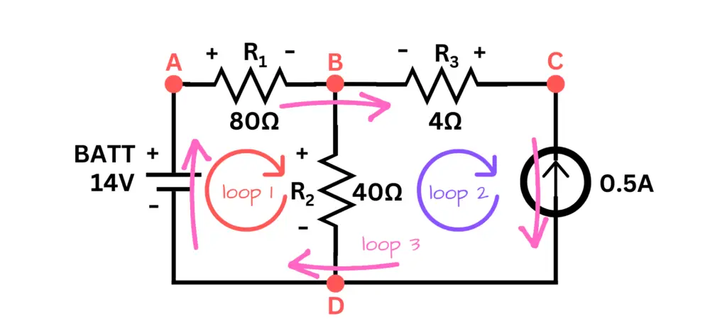
Recall that a loop is any closed path in a circuit. Observing the image of our circuit below, we see that there are 3 loops in total: 1 red loop, 1 purple loop, and 1 pink loop
Solving for Problem c):
Recall that a mesh is a loop that does not contain any other loops. Observing the image of our circuit below, we see that there are 2meshes in total:

Solving for Problem d):
To solve for the node voltages in the circuit, we use nodal analysis.
There are two types of nodes in nodal analysis:
- Non-reference node: A node that has a definite node voltage.
- Reference node: A node that references a point for all other nodes, such as a ground reference.
Node D (Reference Node):
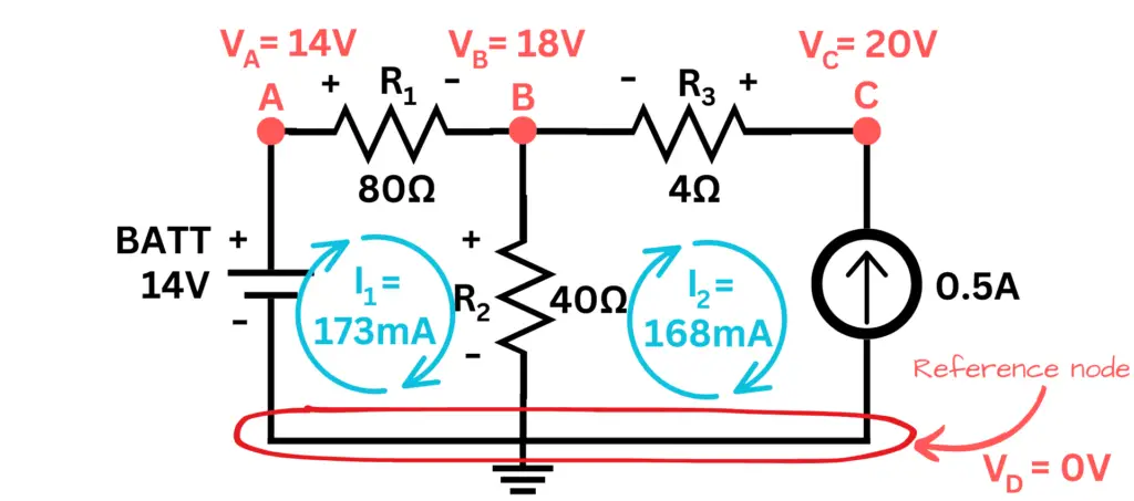
For our circuit example, we’ll use the bottom node or node D, as our reference node or ground for all the other nodes in the circuit to refer to. This means that node D, or the reference node voltage, or ground will be zero volts (0V).
\begin{equation}
V_D = V_{ref} = V_{GND} = 0V
\end{equation}
\begin{equation}
\boxed{V_D\space =\space 0V}
\end{equation}

Node A:
To determine the voltage at a node, we must consider where the node is located in the circuit. Node A, for example, is located at the positive terminal of the voltage source or battery (Vbatt = 14V). There are no other components between the positive terminal of the battery and node A, so node A must be +14V.
\begin{equation}
V_{batt} = 14V
\end{equation}
\begin{equation}
\boxed{V_A = 14V}
\end{equation}
Node B:
First, let’s recall Kirchoff’s Current Law:
- Kirchoff’s Current Law (KCL): KCL is a statement of the conservation of charge. It says that for charge to be conserved, the sum of of currents entering a node must equal to the sum of the currents exiting that node.
- If you’re unfamiliar with the concept of KCL, I recommend that you visit our page on Kirchoff’s Current Law here.
- We’ll use KCL to solve for the values of the node voltages in the circuit.
To determine the voltage at node B, we need to consider the currents entering node B and the currents exiting node B. We’ll apply KCL to obtain the voltage at node B.
- Step 1: First, I’m going to label each branch connected to node B, as shown in the image of our circuit below. Normally you wouldn’t do this step, but I am in order to make the process of explaining the following concepts to you be more clear.
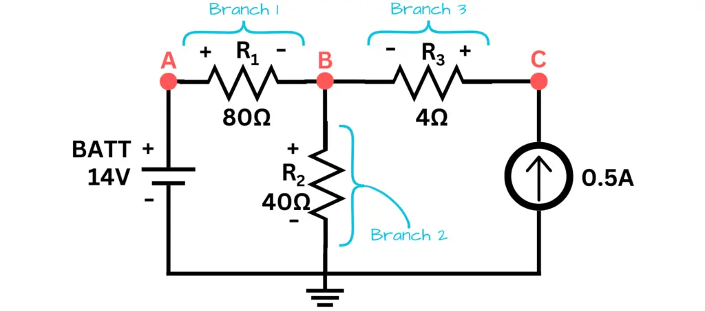
- Step 2: I’m also going to use Ohm’s Law to create an equation of the summation of currents entering or exiting node B and set those values equal to zero. Note that we don’t know any current values or their directions in the circuit — they weren’t given to us — even though we’re given polarities across each component in the circuit.
(Current thru branch 1 to/from node B) + (Current thru branch 2 to/from node B) + (Current thru branch 3 to/from node B) = 0
Referring to the image of our circuit in step 1 above, our equation for node B becomes:
\begin{equation}
I_{(thru\space branch\space 1)}\space +\space I_{(thru\space branch\space 2)}\space +\space I_{(thru\space branch\space 3)}\space =\space 0
\end{equation}
Recall Ohm’s Law: V = IR, the current is represented as:
\begin{equation}
I = \frac{V}{R}
\end{equation}
For the voltage, we must take the difference of voltages across each component in each branch to account for the voltage drop across the branch leading to node B:
\begin{equation}
\frac{(V_A\space -\space V_B)}{R_1} + \frac{(0\space -\space V_B)}{R_2} + \frac{(V_C\space -\space V_B)}{R_3}\space =\space 0
\end{equation}
Substituting known values:
\begin{equation}
\frac{(14V\space -\space V_B)}{80Ω} + \frac{(-\space V_B)}{40Ω} + \frac{(V_C\space -\space V_B)}{4Ω}\space =\space 0
\end{equation}
Multiplying both sides of the equation by 80:
\begin{equation}
{(14V\space -\space V_B)}\space -\space {2V_B}\space +\space {20(V_C\space -\space V_B)}\space =\space 0
\end{equation}
Distributing values and removing the unit for voltage (on 14V) for simplicity:
\begin{equation}
{14\space -\space V_B}\space -\space {2V_B}\space +\space 20V_C\space -\space 20V_B\space =\space 0
\end{equation}
Combining like terms:
\begin{equation}
14\space -\space 23V_B\space +\space 20V_C\space =\space 0
\end{equation}
Rearranging to solve for the voltage at node B:
\begin{equation}
-23V_B\space =\space -20V_C\space -\space 14
\end{equation}
Dividing both sides of the equation by -23:
\begin{equation}
V_B\space =\space \frac{-20}{-23}V_C\space -\space \frac{14}{-23}
\end{equation}
\begin{equation}
V_B\space =\space \frac{20}{23}V_C\space +\space \frac{14}{23}
\end{equation}
From here, we don’t know the value of the voltage at node C (VC) yet. At this point, we’ve simplified as far as we can for this equation. We’ll keep it here for now and move on to solve for the voltage at node C — later referring back to this equation (equation #14) to solve for the voltage at node B (VB).
Node C:
We’re going to go through the same process with node C as we did with node B. Notice that I’ve labeled branch 4 now, as shown in the image of our circuit below:

Now, I’m going to use Ohm’s Law to create an equation of the summation of currents entering or exiting node C and set those values equal to zero. Notice that there are only two branches connected to node C:
(Current thru branch 3 to/from node C) + (Current thru branch 4 to/from node C) = 0
\begin{equation}
I_{(thru\space branch\space 3)}\space +\space I_{(thru\space branch\space 4)}\space =\space 0
\end{equation}
Recall Ohm’s Law: V = IR, the current is represented as:
\begin{equation}
I = \frac{V}{R}
\end{equation}
For the voltage, we must take the difference of voltages across each component in each branch to account for the voltage drop across the branch leading to node C:
\begin{equation}
\frac{(V_B\space -\space V_C)}{R_3}\space +\space 0.5A\space =\space 0
\end{equation}
Notice in the equation for the current through branch 4 from the current source — the value is positive (plus) 0.5 amps (0.5A). This is because the current source given in our circuit shows that the current is pointing toward or into node C. We use the convention: current entering a node is positive and current exiting a node is negative.
Let’s do a bit more algebra, remove the unit for amps (A) for simplicity, and get the voltage for node C (VC) to one side:
\begin{equation}
\frac{V_B}{R_3}\space -\space \frac{V_C}{R_3}\space +\space 0.5\space =\space 0
\end{equation}
\begin{equation}
\frac{V_B}{R_3}\space -\space \frac{V_C}{R_3}\space =\space -0.5
\end{equation}
I’m going to change the decimal value of -0.5 to its rational value of –1⁄2 to make calculations easier later:
\begin{equation}
\frac{V_B}{R_3}\space -\space \frac{V_C}{R_3}\space =\space -\frac{1}{2}
\end{equation}
Multiply both sides by R3:
\begin{equation}
V_B\space -\space V_C\space =\space -\frac{1}{2}R_3
\end{equation}
\begin{equation}
-V_C\space =\space -\frac{1}{2}R_3\space -\space V_B
\end{equation}
Multiplying by -1 to both sides of the equation:
\begin{equation}
V_C\space =\space \frac{1}{2}R_3\space +\space V_B
\end{equation}
Let’s substitute VB with the value we found for the voltage at node B we had from the end of step 2 for node B (equation #14). Here’s the equation for VB again:
\begin{equation}
V_B\space =\space \frac{20}{23}V_C\space +\space \frac{14}{23}
\end{equation}
Substituting VB into our equation from above:
\begin{equation}
V_C\space =\space \frac{1}{2}R_3\space +\space {(\frac{20}{23}V_C\space +\space \frac{14}{23})}
\end{equation}
Removing the braces and writing VC as 23⁄23VC to make addition of fractions simpler:
\begin{equation}
\frac{23}{23}V_C\space =\space \frac{1}{2}R_3\space +\space {\frac{20}{23}V_C\space +\space \frac{14}{23}}
\end{equation}
Rearranging and substituting for R3:
\begin{equation}
\frac{23}{23}V_C\space -\space \frac{20}{23}V_C\space =\space \frac{1}{2}(4Ω)\space +\space \frac{14}{23}
\end{equation}
Removing the unit for ohms (Ω) and combining like terms:
\begin{equation}
\frac{3}{23}V_C\space =\space 2\space +\space \frac{14}{23}
\end{equation}
Converting 2 into a rational with 23 in its denominator makes it become 46⁄23:
\begin{equation}
\frac{3}{23}V_C\space =\space \frac{46}{23}\space +\space \frac{14}{23}
\end{equation}
Adding the fractions:
\begin{equation}
\frac{3}{23}V_C\space =\space \frac{60}{23}
\end{equation}
Multiplying both sides of the equation by 23⁄3:
\begin{equation}
V_C\space =\space \frac{60}{23}(\frac{23}{3})
\end{equation}
\begin{equation}
\boxed{V_C\space =\space 20V}
\end{equation}
Now that we know the voltage at node C, we can now solve for the voltage at node B using our equation at the end of step 2 for node B (equation #14). Here’s the equation for VB again:
\begin{equation}
V_B\space =\space \frac{20}{23}V_C\space +\space \frac{14}{23}
\end{equation}
Substituting the voltage for node C (VC = 20V):
\begin{equation}
V_B\space =\space \frac{20}{23}(20V)\space +\space \frac{14}{23}
\end{equation}
\begin{equation}
V_B\space =\space \frac{400}{23}\space +\space \frac{14}{23}
\end{equation}
\begin{equation}
V_B\space =\space \frac{414}{23}V
\end{equation}
\begin{equation}
\boxed{V_B\space =\space 18V}
\end{equation}
Solving for Problem e):
To solve for the mesh currents in the circuit, we use mesh analysis.
First, we must recall Kirchoff’s Voltage Law:
- Kirchoff’s Volatage Law (KVL): KVL is a statement of the conservation of energy. It says that for energy to be conserved, the sum of the voltage drops across each component around a mesh must equal zero.
- If you’re unfamiliar with the concept of KVL, I recommend that you visit our page on Kirchoff’s Voltage Law here.
- We’ll use KVL to solve for the values of the mesh currents in the circuit.
- Step 1: Stepping around mesh 1 in a clockwise fashion, we’ll use Ohm’s Law to add up all the voltage drops across each element around the mesh and then set it equal to zero.
Let’s first step around mesh 1:

Mesh1:
\begin{equation}
-14\space +\space I_1R_1\space +\space (I_1\space -\space I_2)R_2\space =\space 0
\end{equation}
Notice that when we walk around mesh 1 we’re following I1. As we approach the branch where R2 is, the currents I1 and I2 are opposing each other as we walk through R2 — hence, we obtain (I1 – I2) for the current through R2, for mesh 1.
Now, we substitute the known values into our equation:
\begin{equation}
-14\space +\space I_1(80Ω)\space +\space (I_1\space -\space I_2)40Ω\space =\space 0
\end{equation}
Distributing values and combining like terms:
\begin{equation}
-14\space +\space 80I_1\space +\space 40I_1\space -\space 40I_2\space =\space 0
\end{equation}
\begin{equation}
-14\space +\space 120I_1\space -\space 40I_2\space =\space 0
\end{equation}
Solving for I1:
\begin{equation}
120I_1\space =\space 14\space +\space40I_2
\end{equation}
Dividing both sides of the equation by 120:
\begin{equation}
I_1\space =\space \frac{14}{120}\space +\space\frac{40}{120}I_2
\end{equation}
From here, we don’t know the value of the current I2 yet. At this point, we’ve simplified as far we want to go for this equation. We’ll keep it here for now and move on to solve for the current I2 — later referring back to this equation (equation #43) to solve for the current I1.
Now, let’s step around mesh 2.
- Step 2: Stepping around mesh 2 in a clockwise fashion, we’ll use Ohm’s Law to add up all the voltages across each element for the mesh and then set it equal to zero.
Let’s first step around mesh 2:

Mesh 2:
\begin{equation}
(I_2\space -\space I_1)R_2\space +\space I_2R_3\space -\space 0.5A\space =\space 0
\end{equation}
Notice that when we walk around mesh 2 we’re following I2. As we approach the branch where R2 is, the currents I2 and I1 are opposing each other as we walk through R2 — hence, we obtain (I2 – I1) for the current through R2, for mesh 2.
Also note, that as we walk through the branch of the circuit that contains the current source, we are walking against its current of 0.5A. The arrow shown for the given current source is pointing the opposite direction of the path of I2, the current we’re following in mesh 2 — hence, we obtain -0.5A.
Now, we substitute the known values into our equation:
\begin{equation}
(I_2\space -\space I_1)R_2\space +\space I_2R_3\space -\space 0.5A\space =\space 0
\end{equation}
\begin{equation}
(I_2\space -\space I_1)40Ω\space +\space I_2(4Ω)\space -\space 0.5A\space =\space 0
\end{equation}
Distributing and removing the units:
\begin{equation}
40I_2\space -\space 40I_1\space +\space 4I_2\space -\space 0.5\space =\space 0
\end{equation}
Combining like terms, converting the decimal value 0.5 into its rational value of 1⁄2 and solving for I2:
\begin{equation}
44I_2\space -\space 40I_1\space -\space \frac{1}{2}\space =\space 0
\end{equation}
\begin{equation}
44I_2\space =\space \frac{1}{2}\space + \space 40I_1
\end{equation}
Dividing both sides of the equation by 44:
\begin{equation}
I_2\space =\space (\frac{1}{44})\frac{1}{2}\space + \space \frac{40}{44}I_1
\end{equation}
\begin{equation}
I_2\space =\space \frac{1}{88}\space + \space \frac{40}{44}I_1
\end{equation}
Now, let’s take our equation at the end of step 1 (equation #43) for mesh 1 — where we solved for I1, but didn’t know I2 yet — and substitute I1 into our equation above to solve for I2. Our equation for I1 was:
\begin{equation}
I_1\space =\space \frac{14}{120}\space + \space \frac{40}{120}I_2
\end{equation}
Substitute I1 into our equation for I2 above:
\begin{equation}
I_2\space =\space \frac{1}{88}\space + \space \frac{40}{44}(\frac{14}{120}\space + \space \frac{40}{120}I_2)
\end{equation}
Distributing the value 40⁄44 into the parenthesis:
\begin{equation}
I_2\space =\space \frac{1}{88}\space + \space (\frac{560}{5280}\space + \space \frac{1600}{5280}I_2)
\end{equation}
Simplifying and converting I2 into 5280⁄5280I2 for simplifying calculations, then combining like terms and solving for I2:
\begin{equation}
\frac{5280}{5280}I_2\space =\space \frac{1}{88}\space + \space \frac{560}{5280}\space + \space \frac{1600}{5280}I_2
\end{equation}
\begin{equation}
\frac{3680}{5280}I_2\space =\space \frac{1}{88}\space + \space \frac{560}{5280}
\end{equation}
Converting 1⁄88 into 60⁄5280 for simplifying calculations:
\begin{equation}
\frac{3680}{5280}I_2\space =\space \frac{60}{5280}\space + \space \frac{560}{5280}
\end{equation}
\begin{equation}
\frac{3680}{5280}I_2\space =\space \frac{620}{5280}
\end{equation}
\begin{equation}
I_2\space =\space (\frac{5280}{3680})\frac{620}{5280}
\end{equation}
\begin{equation}
I_2\space =\space \frac{620}{3680}A
\end{equation}
\begin{equation}
\boxed{I_2\space =\space 0.168A}
\end{equation}
\begin{equation}
\boxed{I_2\space =\space 168\space mA}
\end{equation}
The positive value of current for I2 tells us that the current is actually going in the direction we walked around in mesh 2 — the current is going clockwise around the mesh.
Now that we know the value for I2, we can solve for the mesh current I1 using the equation at the end of step 1 for mesh 1 (equation #43):
\begin{equation}
I_1\space =\space \frac{14}{120}\space +\space \frac{40}{120}I_2
\end{equation}
Substituting our value for I2 and solving for I1. The following values will be approximations, since we’ll be dealing with decimals:
\begin{equation}
I_1\space =\space \frac{14}{120}\space +\space \frac{40}{120}(0.168A)
\end{equation}
\begin{equation}
I_1\space =\space \frac{14}{120}\space +\space (0.056)
\end{equation}
\begin{equation}
I_1\space =\space 0.117\space +\space 0.056
\end{equation}
\begin{equation}
\boxed{I_1\space =\space 0.173A}
\end{equation}
\begin{equation}
\boxed{I_1\space =\space 173\space mA}
\end{equation}
The positive value of current for I1 tells us that the current is actually going in the direction we walked around in mesh 1 — the current is going clockwise around the mesh.
Solutions to the Questions for the Circuit Problem Above
- How many nodes are there in this circuit? 4 nodes
- How many loops are there in this circuit? 3 loops
- How many meshes are there in this circuit? 2 meshes
- Using nodal analysis, solve for the node voltages in the circuit. VA = 14V, VB = 18V, VC = 20V, VD = 0V
- Using mesh analysis, solve for the mesh currents in the circuit. I1 = 173mA, I2 = 168mA
Conclusion
To begin our understanding of circuit nodes, loops and meshes, we started off with the basics. We reviewed circuit elements and their uses in constructing electrical circuits. We also reviewed branches in circuits and their concept of creating a path between two nodes through which electrical energy can flow. Each topic building a foundation to better understand completely the concepts of circuit nodes, loops and meshes.
If you’ve gone through everything presented on this page, you now have a solid understanding of circuit nodes, loops and meshes. You’ve learned to calculate the node voltages of circuits using node analysis and you’ve learned to calculate mesh currents using mesh analysis.
If you are eager to further your knowledge on circuit theory or have a hankering for building your own electronics or robotics projects, I suggest you browse more throughout our site. We offer loads of content that has been meticulously created in order to help you completely understand the concepts of whatever topic you desire pertaining to electronics and robotics. Thank you for your interest — remember, keep at it and stay motivated!
Frequently Asked Questions
Q1.) Which should I use when solving for mesh currents — nodal analysis or mesh analysis?
You should use mesh analysis for solving for mesh currents. Use nodal analysis when solving for node voltages.
Q2.) It stated that the mesh currents for I1 and I2 are both going in the clockwise direction, according to the outcomes of the values you calculated for them. The source current shows that its current is pointing toward the opposite direction or against the actual flow of current. What’s happening there? Why is the current not actually flowing in the direction that the source current is pointing?
An explanation for this is that the battery of this circuit is probably overpowering the current source and is able to oppose its current against the sources current. Something to keep in mind here for problems given like this is that they are not always representations of real-world circuits — they are often just circuits made “on paper” to practice your abilities to perform the calculations being taught, as in our example circuit above was.