Electronics Project: The Chewing Gum Box LED Night Light
| Project Name: | The Chewing Gum Box LED Night Light |
| Project Description: | Building a simple parallel LED circuit |
| Project Difficulty: | Easy |
| Project Note: | This project uses a soldering iron, but this is optional. See FAQs at bottom of page for alternatives. |
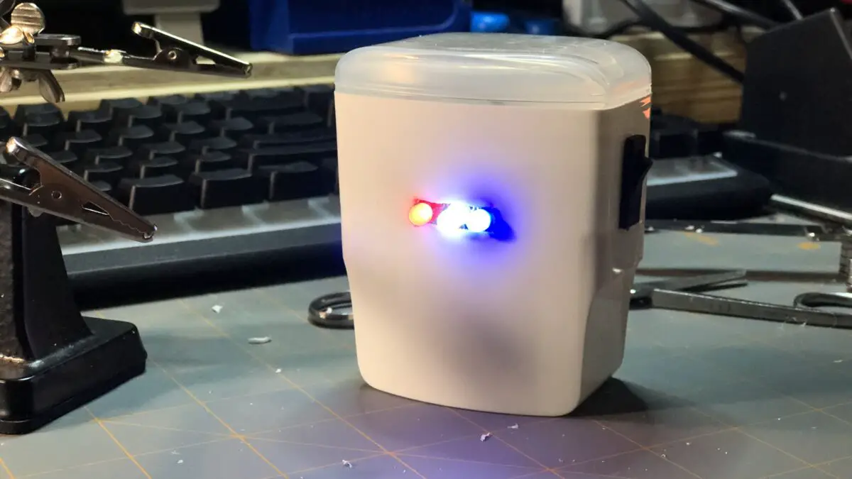
In this project, we’re going to make a battery powered LED night light out of a chewing gum box — like the ones you get in the aisle of a grocery store or convenient store. This kind of project is super-easy and is a great way to learn how to use basic electronic components to make something useful.
The chewing gum box night light we’ll be making is a great way to get kids involved in electronics. Not only is it cute for kids, but it’s portable too!
Where The Design Came From
I decided to come up with this design because my daughter saw me tinkering one day with some LEDs and asked me if we could make her a night light out of them. So, I started work on making this simple design we’ll use here in this blog post. All the photos and video you’ll see here is the exact night light I made for my daughter.
Let’s Be Methodical
I like to be very methodical about things, so we’ll go step-by-step — in detail — on the entire build of this project: the parts we’ll need, why we’re using them, how to connect them, how they work, and more! First, we’ll start with the following parts list:
Parts List
| Item | Quantity | Description |
| Wrigley’s Extra Refreshers® Chewing Gum Box | 1 | This is our makeshift project box to contain all of our electronic components. |
| Alternative Project Box (if you cannot find a chewing gum box) | 1 | This can be an alternative option if you can’t find a chewing gum box. |
| Red LED – 5mm Diffused | 1 | 1-of-3 LEDs for this project. |
| White LED – 5mm Diffused | 1 | 1-of-3 LEDs for this project. |
| Blue LED – 5mm Diffused | 1 | 1-of-3 LEDs for this project. |
| 820Ω Resistor | 3 | We use these to limit the current through our LEDs. Recall Ohm’s Law: V = IR |
| SPST Rocker Switch | 1 | This is our simple ON/OFF switch. |
| 9V Battery | 1 | This is our power source. |
| 9V Battery Snap Connector | 1 | This makes connecting our battery to the circuit easier. |
| PCB Prototype Board 4 x 6 cm | 1 | We use this to solder our components together onto one board. |
| Hot-glue Gun with Hot-glue Stick | 1 each | We use these to attach the PCB board to the interior of the chewing gum box (project box). |
(Optional) Breadboard Prototyping Parts List
| Item | Quantity | Description |
| Solderless Breadboard | 1 | You can use either an 830-point or a 400-point solderless breadboard for testing purposes. |
| Jumper Wires | Several Miscellaneous Sizes | We use these to make solderless connections to our components on the breadboard. |
Prototyping the Circuit
Before taking our parts and haphazardly soldering them together on our PCB prototype board, it’s good practice to first “dry-fit” our components — or temporarily put together our circuit on a breadboard.
If you need to — you may check out our Breadboard Basics page here to understand the breadboard and how to use one.
You can skip this part if you’d like and go straight to the videos of the solderable PCB prototype board build for this project below.
Steps 1 – 7: How To Prototype The Chewing Gum Box LED Night Light Circuit
The following is a step-by-step process on how to put your components together on a breadboard to test to see if your circuit works before placing them permanently onto a solderable PCB prototype board.
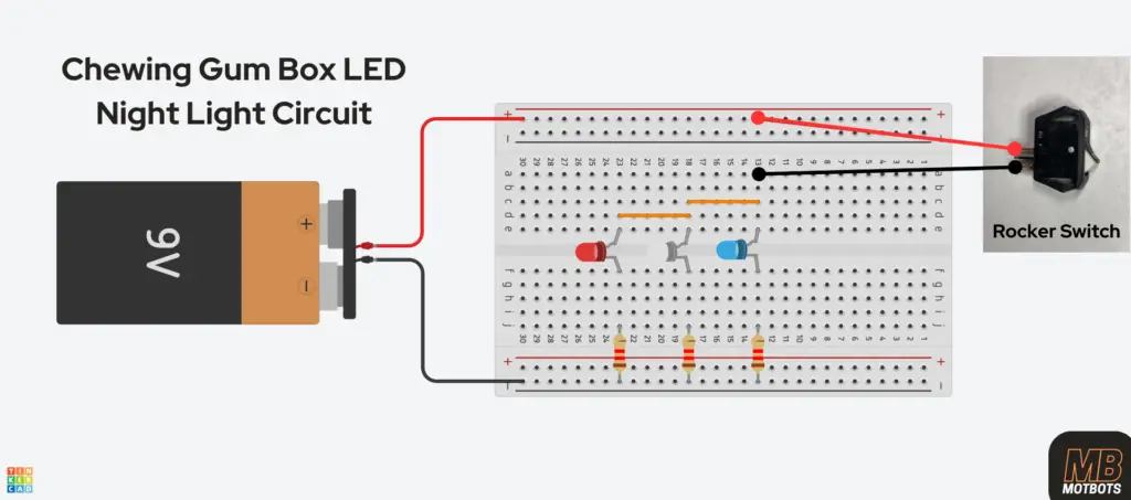
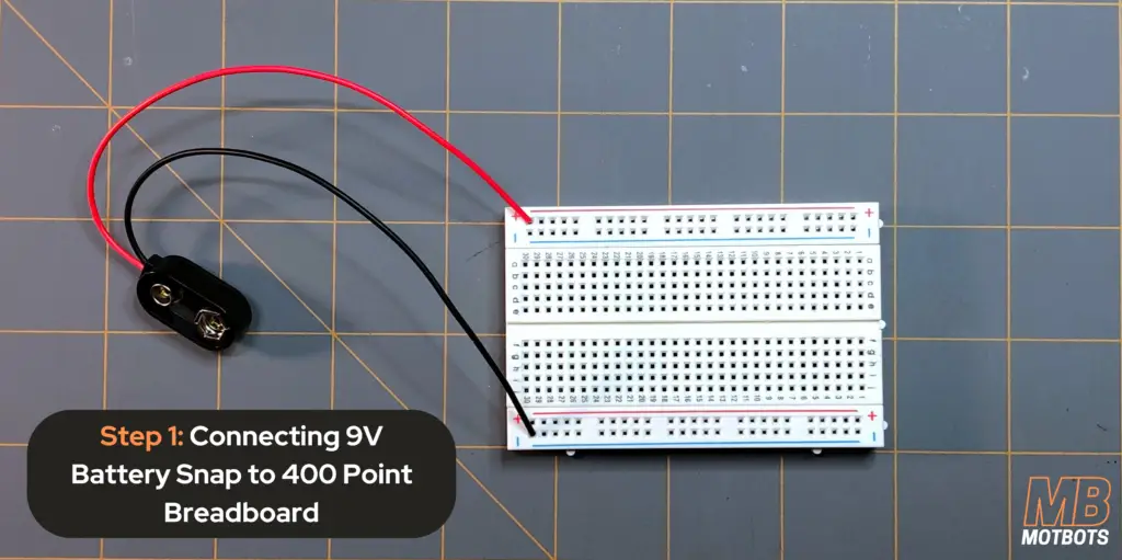
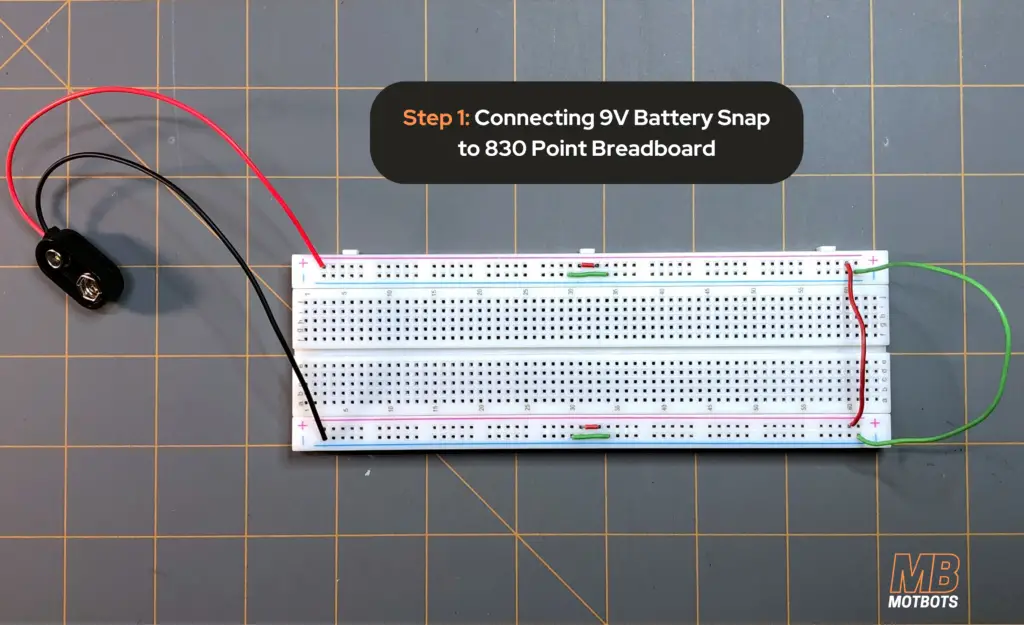
- Breadboard Setup: First, take your breadboard and set it up for power — but DO NOT connect your battery or other power supply to it yet. I’ve shown you how to do this for either a 400 point or an 830 point breadboard. I used the 830 point breadboard for my test circuit, although the simulation circuit above shows a 400 point breadboard setup.
- 400 Point Breadboard: Connect the positive (red) terminal of the 9V battery snap connector to a positive (+) line of points on either outer edge of the breadboard — this will be our positive supply. Connect the negative (black) terminal of the 9V battery snap connector to a negative (-) line of points on the opposite outer edge of the breadboard — this will be our negative supply.
- 830 Point Breadboard: Connect the positive (red) terminal of the 9V battery snap connector to a positive (+) line of points on either outer edge of the breadboard — this will be our positive supply. Connect the negative (black) terminal of the 9V battery snap connector to a negative (-) line of points on the opposite outer edge of the breadboard — this will be our negative supply. We must also continue the connection of both positive (+) and negative (-) supplies of our breadboard down its other half on both sides of the board using jumper wires.
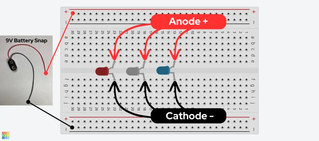
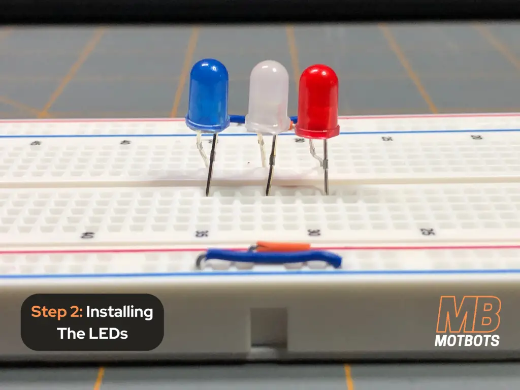
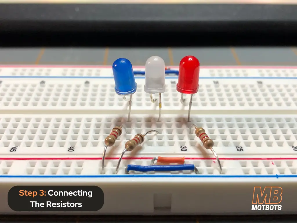
- Installing The LEDs: For this example — I am using red, white and blue LEDs at my daughter’s request, but you can use all white LEDs or whatever color combination you prefer. We will place the LEDs side-by-side across the center groove of the breadboard — making sure to point all the anode (+) terminals toward one side of our breadboard and all the cathode (-) terminals toward the other side of our breadboard, as shown:
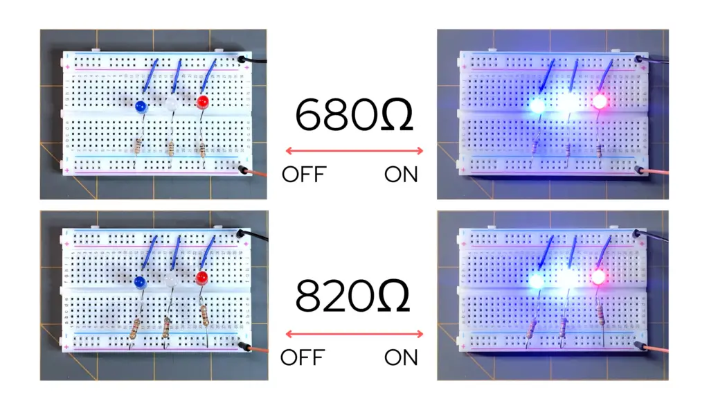
- Connecting The Resistors: For this example — I am using 1200Ω resistors to limit the current to each of the LEDs. I tested the LEDs with 680 Ω resistors and thought the LEDs to be too bright for a night light. The 820 Ω resistors made the LEDs less bright, but still too bright for sleep if my daughter kept the night light near herself.
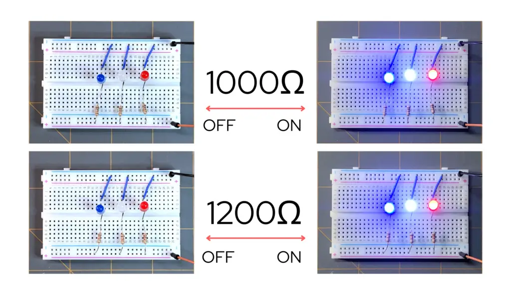
- So I tried the 1000 Ω resistors on the LEDs and thought them to be about the right amount for brightness. You could still see just fine in the dark, but I was looking for something still a little more subtle in brightness for my daughter’s night light. So, I chose the 1200 Ω resistors. You can choose whatever size resistors you like — just keep in mind that smaller values in resistance may reduce battery life. We’ll measure this later.
Note that resistor orientation in a circuit does not matter. Resistors conduct current in either direction.
| Resistor Size in Ohms (Ω) | Tested Battery Voltage (V) | Measured Total Circuit Current (A) | Calculated Total Circuit Power (W) (P = IV) | Objective LED Brightness | Estimated Battery Life – Constant ON Conditions [rounded to nearest whole number] |
| 680 Ω | 9.28 V | 28.5 mA | 264 mW | Brightest – Almost blinding | 21 hrs |
| 820 Ω | 9.28 V | 23.9 mA | 222 mW | Bright | 25 hrs |
| 1000 Ω | 9.28 V | 19.5 mA | 181 mW | Bright enough to see in dark | 31 hrs |
| 1200 Ω | 9.28 V | 16.4 mA | 152 mW | Soft glow | 37 hrs |
LED Comparison Test for Brightness
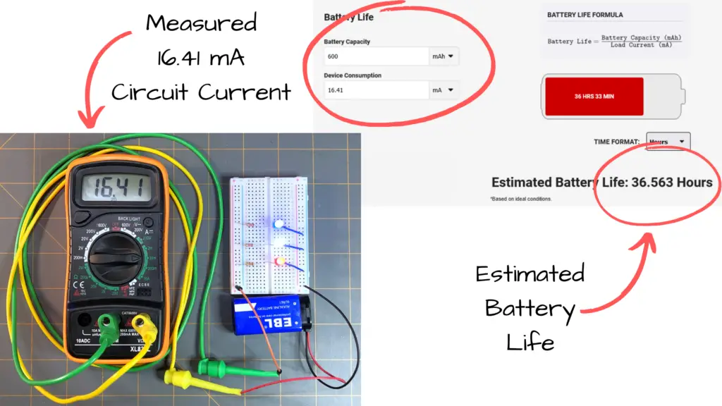
To obtain the battery life I used DigiKey’s Battery Life Calculator. Keep in mind that these battery life calculations are estimated based on ideal conditions.
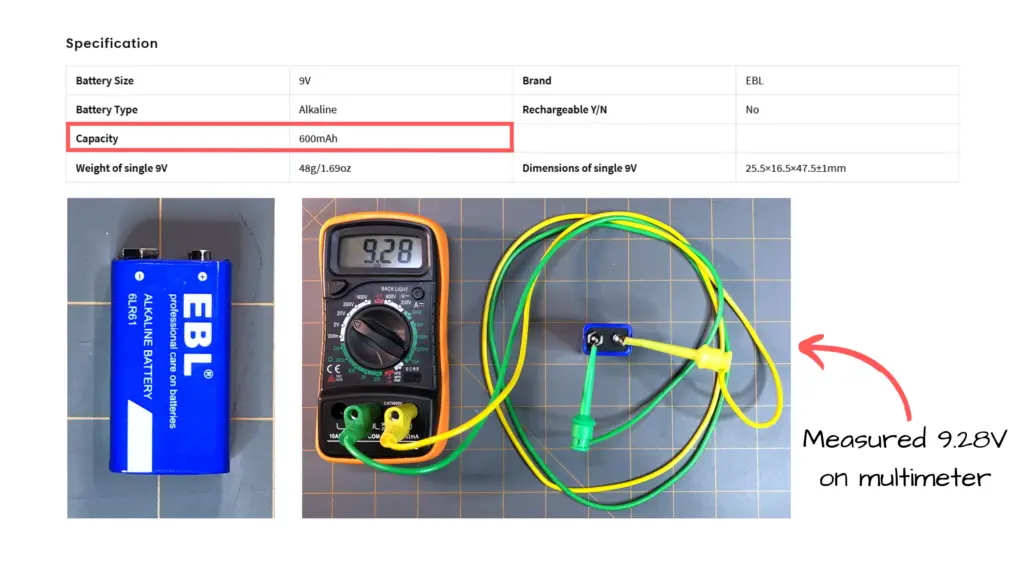
I found my EBL 9V battery specifications at EBL’s website. This gave me the battery capacity of my battery, which is 600 mAh. I measured my battery voltage with my multimeter and found it to be at 9.28V, as seen in the image below.
I found the device consumption by measuring the total circuit current with my multimeter.
With these values, I used DigiKey’s Battery Life Calculator, and was able to obtain an estimate as to how long I could expect my battery to last — as shown in the image below:
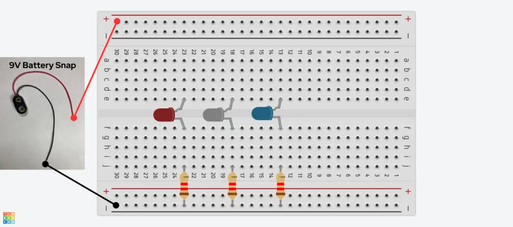
So, we’ve chosen our resistors and now it’s time to place them in our breadboard circuit. For this circuit, we’re going to be connecting our LEDs in parallel. All you have to do is connect one terminal of each resistor to each of the cathode (-) terminals of the LEDs. Then, connect the other terminal of each resistor to the negative supply of the breadboard.
- Connecting The Anodes (+) of The LEDs: Next we need to connect each of the anodes of the LED’s together. We do this because we’re connecting our LEDs in parallel.
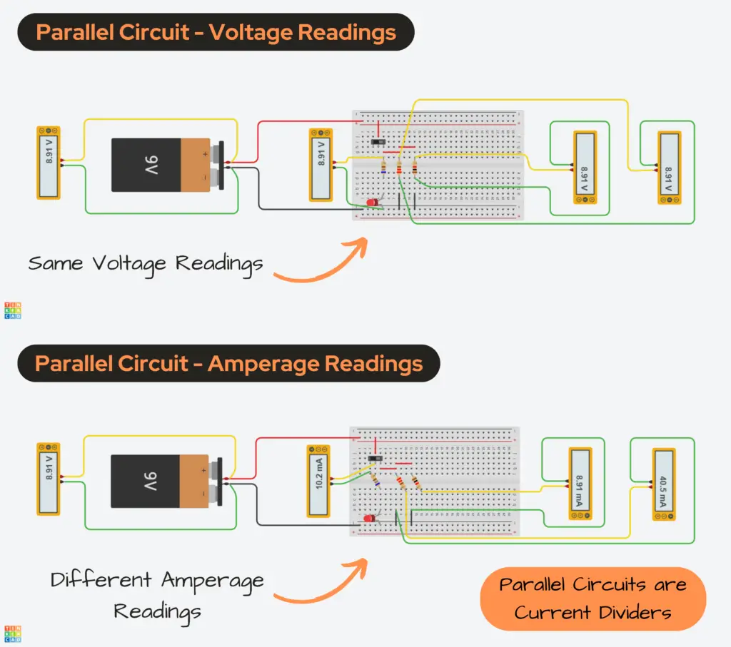
- We are connecting our LEDs in parallel because we want all of our LEDs to be of similar brightness and receive the same voltage potential.
A parallel circuit is a current divider, but the voltage is the same across each branch of the circuit.
Example Parallel Circuit and Its Readings
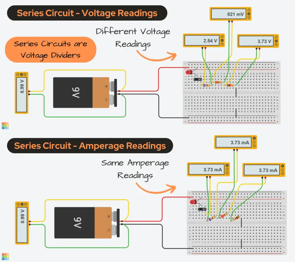
- If we were to connect our LEDs in series, each LED in line would gradually get dimmer and dimmer because of the voltage drop across each LED and the resistor in the circuit.
A series circuit is a voltage divider, but the current is the same through each component in the circuit.
Example Series Circuit and Its Readings
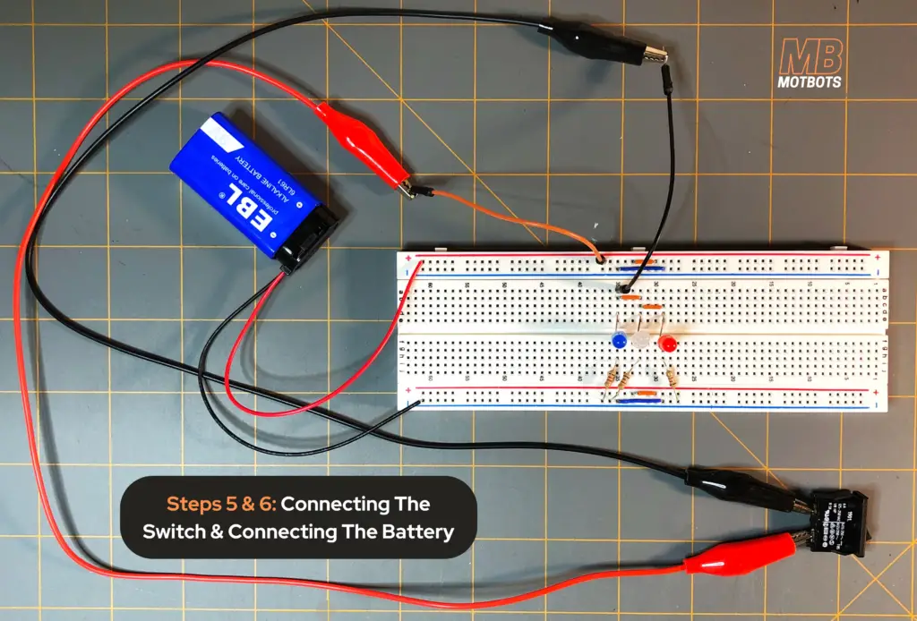
- Connecting The Switch: Now, to be able to control our circuit and complete it — we need to connect the switch. If you need to know more about connecting switches to a circuit, check out our Simple Switch Circuit page here.
- To do so in this setup, I’ve connected a couple of jumper wires — one to the positive supply (orange wire) and one (black wire) to a point in line with the anode of the blue LED and small orange parallel jumper wire.
- Connecting The Battery: Next, we need to connect our battery to the battery snap connector. There is only one way to connect these — since the positive (+) terminal of the 9V battery is a small male button stud and the negative (-) terminal of the 9V battery is a larger female button stud.
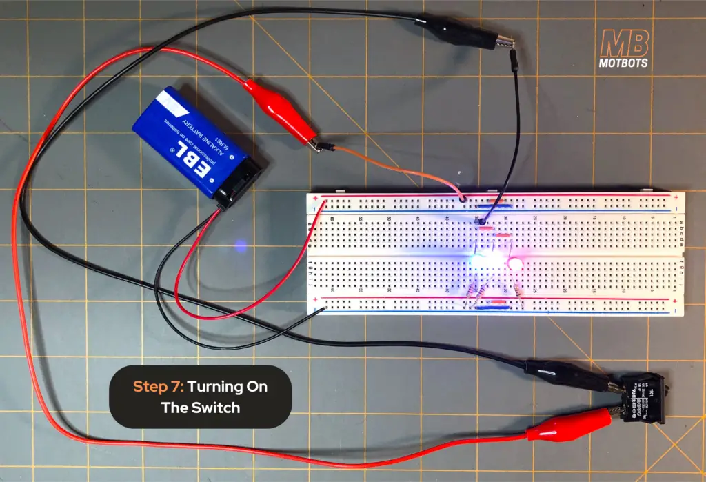
- Turning On The Switch: Now our circuit is complete! Time to test it to see if it works — go ahead, turn it ON at the switch. Did the LEDs light up?
4 Checks to Troubleshooting Your Breadboard Prototype Circuit
If your LED’s did not light up in your breadboard circuit, let’s perform a troubleshoot to see what may be the issue:
- Check Battery Voltage: First, check that you have the proper battery voltage. We are using a 9 volt battery for this circuit, so it needs to have a potential of at least 9V or more. To check your battery voltage you can go to our Multimeters in a Nutshell page here.
- Check Battery Connection: Check that your battery snap terminals are properly connected to the breadboard — positive (red) terminal to positive supply line and negative (black) terminal to negative supply line.
- Check Circuit Component Connections: Make sure that all components are connected properly. Refer back to the images in the steps above to reassure yourself. If you need to you may check out our Breadboard Basics page here to understand the breadboard and how to use one.
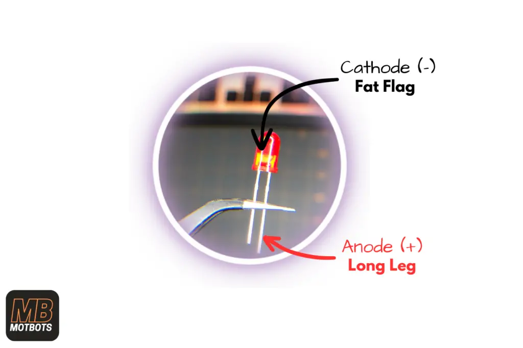
- Check LEDs: Make sure you have your LEDs in the correct orientation. If you need help with this, check out our Fundamentals of Electronics: LEDs page here to learn proper LED circuit orientation.
Video Build of The Circuit on a PCB Board
Now, let’s get to building our permanent circuit for our Chewing Gum Box LED Night Light. We’ll first need to decide where we want to place all our components on the PCB board and where we’ll make our positive and negative supply distribution lines on the PCB from our 9V battery.
You can choose how you want your placement of all the components on your own PCB board — or you can follow along with how I did my own — just be sure to connect all the components properly as how I’ve described in the breadboard test build and the circuit diagram provided below:
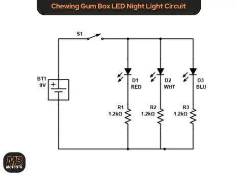
Part 1
Part 2
Conclusion
Now that you’ve built this simple circuit successfully, you’re now well equipped to start designing and making your own simple circuits. In this project, you learned how a circuit works, how to include a switch and LEDs in a circuit, how to perform simple resistor calculations, and you’ve gained some soldering skills! You’re that much closer to your goals! Remember to stay motivated and keep at it!
Frequently Asked Questions
Q1.) Why are my LEDs not lighting up?
The following are a few possibilities why your LEDs may not be lighting up:
- Improper LED orientation: Make sure you have oriented your LEDs correctly in your circuit. You can see how LEDs are properly oriented by visiting our post on LEDs here.
- Burnt out or defective LEDs: To check to see if your LEDs have been burnt out or are defective in some way you can use the diode test function on a multimeter or create a simple LED test circuit on a breadboard — both of which you can find how to do on our Multimeters in a Nutshell page here.
NOTE: To perform these procedures, you’ll have to remove your LEDs from the circuit. If you’ve soldered your LEDs you will have to either desolder them to remove them from your PCB board or start over again and build yourself a new circuit.
- Improper resistor value or short circuit: If your LEDs are burnt out, make sure you have the proper resistor values and that the resistors are properly connected in your circuit. If they are not, you may have a short somewhere in your circuit. Please refer to the how-to video and wiring diagram above under “Video Build of The Circuit on a PCB Board”.
- Improper wiring or component connection: Your LEDs may not work due to improper connection of components in your circuit. If they are, don’t worry. Messing up is all part of the learning process. We all do it. Please refer to the how-to video and wiring diagram above under “Video Build of The Circuit on a PCB Board” to review how to create this circuit.
Q2.) My LEDs are too bright. How can I make them less bright?
If your LEDs are too bright, you may not have used a large enough resistor value for each of your LEDs. You can choose higher resistor values — experiment with different resistor values — to see which resistor value you like best for the brightness you perceive from your LEDs.
NOTE: If you’ve soldered your resistors you will have to either desolder them to remove them from your PCB board or start over again and build yourself a new circuit.
Q3.) Can I use different resistor values for each individual LED?
Sure! In fact, I encourage you to experiment with resistor values on your project. Using the breadboard you can easily change resistor values out and test your own configuration of resistor values for each individual LED. You may notice some very intriguing outcomes as to how each LED lights up differently or some may not even light up at all, depending on resistor values to specific LED colors. Go ahead, try it out!
Q4.) I don’t have a chewing gum box. What else can I use?
You don’t have to use a chewing gum box like the one used in this project to complete this project yourself. You can use whatever you can find — such as a small food storage container, other small plastic storage container, an old medicine or supplements container, a small wood box, or even a small cardboard box. Just make sure that whatever you use, that it’s non-conductive — that you’re not using a metal container. If you do use something like a metal container, you’ll have to insulate it in some way from your circuit. Also note that whatever you use, make sure that it’s properly cleaned. Hack whatever you have to to make your project unique!
Q5.) I don’t have a solder iron. What else can I do to make this project work?
If you don’t have a solder iron, that’s OK! You don’t have to have one to complete this project. You can just use your breadboard, like we did under “Prototyping the Circuit” above. I suggest you use a 400 point breadboard if you plan on keeping your circuit intact for a long period of time, so that you’re not using so much space and it’s a little more portable.
Q6.) What if I don’t have a breadboard or a solder iron? Can I still make this project?
If you don’t have either a solder iron or a breadboard, don’t fret! You can still complete this circuit! I made a BONUS video below, just for you to show you how you can still build this circuit without a breadboard or a solder iron.
VIDEO COMING SOON!
Did you like this? Please consider buying us a coffee to keep us awake for more!