
How Components Work Together in Real Circuits: Having Components Join Forces
The following is Part 3, of a planned 12 part super series on the topic of components. We started with what components are, then we learned how to decipher their symbols to read circuit schematic diagrams — now we’re moving onto the topic of how these components work together in real circuits.
Later, we’ll progressively work through more topics and ideas of components, further advancing these ideas into a robot project to really get you to understand how they work together to create something awesome and useful.
The following is how this 12 Part Super Series on Components will progress, in order:
- What Is a Component?
- Understanding Circuit Symbols and Schematics
- How Components Work Together in Real Circuits (⬅️ YOU ARE HERE)
- Putting Components to Work
- Introducing Microcontrollers
- Smart Circuits Meet AI
- Teaching Robots to Move
- How Sensors, Data, and AI Create Perception
- Human–Robot Interaction
- Decision Making and Autonomy in Robots
- Robotic Navigation
- Distributed Robotics, Swarms, and Multi-Agent Intelligence
Let’s get started with Part 3: How Components Work Together in Real Circuits
Let Our Powers Combine… GO COMPONENTS!

By now, you’ve met the superheroes of circuits — resistors, capacitors, transistors, and their electric entourage — and you’ve even learned to read their symbols in schematic form.
So… what’s next?
It’s time to see what happens when these components join forces.

A single resistor sitting alone on your desk isn’t going to do much. If you were to make a circuit right now, only containing a resistor connected across a battery’s terminals, you won’t see much happening, but boy will you feel it to the touch — try it!
A resistor on its own isn’t going to save the world, or create a life changing thing-a-ma-jig. You have to team it up with other components – like, give it a sidekick, or more. A component without its sidekicks won’t make much of a circuit, it’ll just turn you into a villain with anger for not working.
Think of it like Batman without Robin, Dr. Strange without Wong, Tick without Arthur the Moth, Jordan without Pippen, Michael Scott without Dwight Schrute, Lucy without Ethel… I think you get the picture — it just doesn’t work!
If you put that resistor with a few friends though, suddenly you’ve got something going on that can do way more. A resistor has its own superpower, but it needs the combination of the other component’s powers to achieve an outcome that’s meaningful.
Components together can be made to do and accomplish all sorts of things. When they come together in the right way, they become the The Circuit Squad!

⚡ Circuits: Where the Magic Happens
A circuit is just a fancy way of saying: “A loop where electricity starts, does something useful, and comes back home.” That’s it!
Every working gadget — from your phone charger to your smart fridge — boils down to one golden rule: electricity has to flow in a complete loop.
Think of it in terms of an arcade game and you (being the gamer that you are) have to win the gaming battle of the century. That arcade machine is all that’s standing in your way to victory — the machine’s circuits must not fail and power to it needs to be consistent. Break the loop and your high score gets dumped into null space. Keep it connected, and you win the game and the bragging rights.
The best way to learn how circuits really work is to play the game yourself. You don’t level up by watching someone else grind — you’ve got to pick up the controller and get in the match. Trust me — this is the kind of grinding that actually feels fun.
So, lets get started with making our first circuit of this series, using simple components to create a circuit with a blinking LED. Once you build that first blinking LED, you’ve officially entered the game world of electronics.
Simple Example: The LED Blinker Circuit (Po-Po Lights)
Let’s put some components together and see how they can team up to do something fun — like making LEDs blink all on their own, forever, without a microcontroller, without a timer chip, and without any “smart” components at all.
Let’s call it: The LED Blinker Circuit (a.k.a. Po-Po Lights). When you use a red and blue LED for this circuit, they tend to look like flashing police lights, which is pretty cool. It’s one of the simplest and most satisfying projects — and a perfect way to see how each component plays a part.
This circuit is a classic two-transistor LED blinker, also known as an astable multivibrator, but don’t worry — you don’t need to memorize that. You can just call it: “The Circuit That Blinks.”

It’s a simple example of components working together as a team to create behavior that none of them can do alone. The following are the items we’ll need to accomplish our goal. Let’s meet the crew of The Circuit Squad.
The Crew:

- Battery (Power Source): It’s the energy provider. The “captain” of the crew.
- Resistor: Limits the current so an LED doesn’t fry. Will also work to pull the transistor collector up to the battery voltage. The “protector/muscle”.
- LED: Lights up when current flows through the circuit. The “illuminator”.
- Capacitor: Stores and releases charge to create timing (like a drummer keeping the beat). The “time keeper”.
- Transistor: Acts as an electronic switch to turn on and off an LED, for example. The “control”.
Parts List for the LED Blinker Circuit
| ITEM | QUANTITY | DESCRIPTION |
| 9V Battery | 1 | The power supply for the circuit. |
| NPN Transistors (e.g. PN2222, 2N3904, BC547, etc.) | 2 | They act like electronic switches that can turn on and off. |
| LEDs (Red and Blue, 3mm or 5mm) | 2 | These light up when their transistor lets current through. |
| 470Ω Resistors (¼ W) | 2 | These limit the current to the LEDs. |
| 47kΩ Resistors (¼ W) | 2 | These pull the transistor collectors up to the battery voltage. |
| 10µF Capacitors (electrolytic, 16V or higher) | 2 | These are the “timers” that create the blinking rhythm. |
This will roughly give you a blink rate of 1.5 times per second. (You can change the 47kΩ resistors or 10µF capacitors later to tweak the blink speed.)
The Cronies:

- Breadboard: Helps make connections between components without soldering them to form circuit prototypes. The “prototyper”.
- Jumper Wires: Helps make connections between the components or help link components together on the breadboard. The “linkers”.
- 9V Battery Snap Connector: Helps connect the 9V battery to the breadboard power rails. The “source connector”.
The Plot:
- The battery pushes current into the circuit.
- The current limiting resistor steps in to slow it down — making sure the LED doesn’t go supernova.
- The capacitor charges up like it’s holding its breath. When full, it releases that charge through the transistor, flipping it on like a switch.
- The transistor then lets current flow through the LED, making it light up.
- Once the capacitor discharges, the transistor turns off again, the LED goes dark, and the cycle starts over.
The Schem-ATIC
The following is the scheme… [clears throat] the schematic for the circuit our crew of components are to assemble as:

The How-To:
Think of the circuit in two main “paths”:
- The LED path: From battery (+9V), to resistor (470Ω), to LED, to transistor (collector).
- The timing path: From battery (+9V), to resistor (47kΩ), to capacitor, to transistor (base).
Now, let’s walk through the steps:
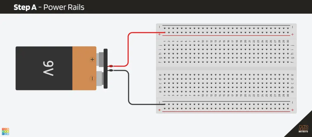
Step A – Power Rails
- Connect the 9V battery + to the red rail on the breadboard.
- Connect the 9V battery – to the blue (ground) rail on the breadboard.
Nothin’ to it so far!
Step B – Transistor placement (Q1 and Q2)
Let’s say you’re using a typical TO-92 NPN package (like a PN2222 or 2N3904): Looking at the flat face, legs downward (left to right), it’s usually:
- Left: Emitter (E)
- Middle: Base (B)
- Right: Collector (C)
⚠️ Double-check the pinout for your specific transistor; some models swap legs.
For example, when looking at the flat face of the BC547, with its legs downward, its pinout reads (from left-to-right):
- Left: Collector (C)
- Middle: Base (B)
- Right: Emitter (E)
Just be sure that you’re paying attention to the orientation of the legs for your specific transistor. I’ll be using the PN2222A type NPN transistor for this particular example, which has the same orientation as the PN2222.
Now:
- Plug the transistors into the breadboard so each of their legs are in a separate row.
- Connect the emitter (E) of each transistor directly to ground. (NOTE: the image of the breadboard circuit below uses an NPN transistor with its pin orientation — reading from left-to-right — as collector (C), base (B), emitter (E))
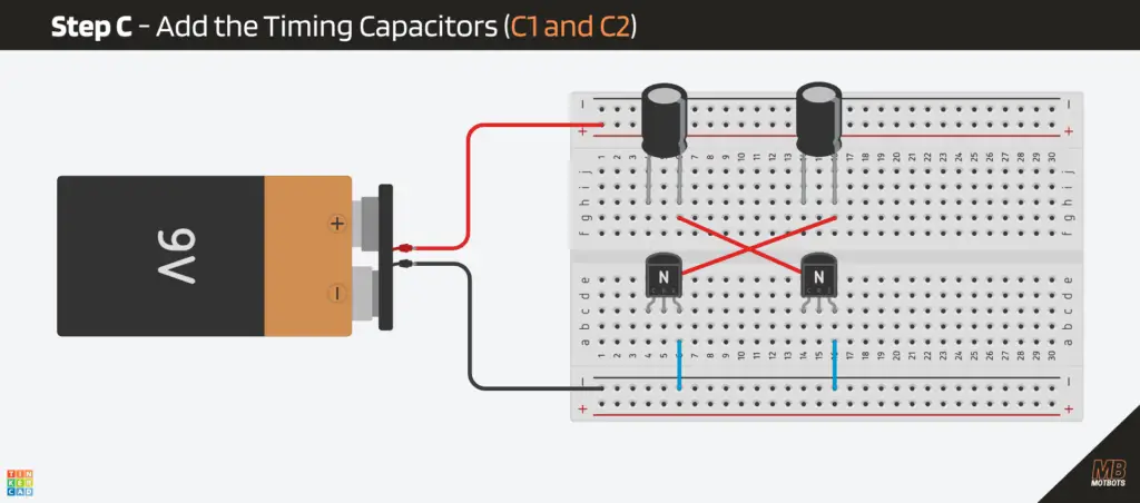
Step C – Add the Timing Capacitors (C1 and C2)
These provide the “kicks” that flip the circuit.
- Take your 10µF electrolytic capacitor and place its negative and positive leads into separate rows, as shown in the image below. Do this for each capacitor.
- For capacitor (C1), take a jumper wire and connect the negative (-) lead to the base (B) of transistor (Q2) — the opposite transistor. (NOTE: The negative (-) lead of a polarized capacitor is usually the one marked with a line, like the gray line of the black body of the 10µF capacitor.)
- For capacitor (C2), take a jumper wire and connect the negative (-) lead to the base (B) of transistor (Q1) — the opposite transistor.
Were beginning to form the timing network that consists of the timing capacitors and their associated transistors. Next, we need to continue to install the LEDs and their current limiting resistors, as well as the timing capacitors to finish out this network.
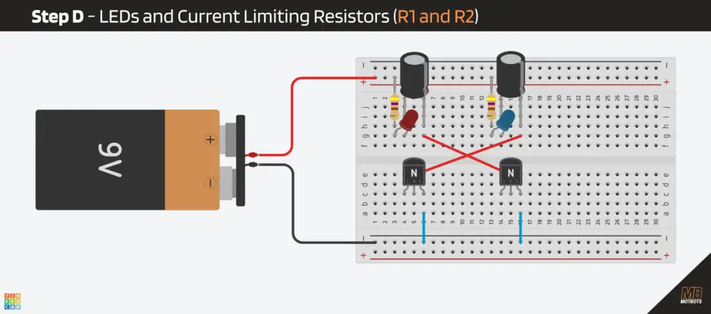
Step D – LEDs and Current-Limiting Resistors (R1 and R2)
We’ll place each LED above their transistors, so each transistor “sinks” current to ground.
- From the +9V rail, place a 470Ω resistor (R1) to an empty row, as shown in the image below.
- Place the red LED so that:
- Its anode (long leg) goes in the same row as its associated 470Ω resistor (R1) output.
- Its cathode (short leg, usually flat side) goes to the same row as the capacitor’s (C1) positive (+) lead is in.
- From the +9V rail, place the other 470Ω resistor (R2) to an empty row, as shown in the image below.
- Place the blue LED so that:
- Its anode (long leg) goes in the same row as its associated 470Ω resistor (R2) output.
- Its cathode (short leg, usually flat side) goes to the same row as the capacitor’s (C2) positive (+) lead is in.
So, as of now, we have the LED path that goes from +9V, to the 470Ω resistor, to the anode of the LED. The cathode of the LED is connected to the anode of the capacitor. This is done for each LED and its associated components, as shown on the circuit schematic from above.
Step E – Add the Timing Resistors (R3 and R4)
These form the cross-coupling network.
- Take a 47kΩ resistor (R3) and place one end of it in the +9V battery rail (red rail) on the breadboard.
- Place the other end of this resistor (R3) at the same row as the capacitor’s (C1) negative (-) lead, as shown in the image below.
- Take your other 47kΩ resistor (R4) and place one end of it in the +9V battery rail (red rail) on the breadboard.
- Place the other end of this resistor (R4) at the same row as the capacitor’s (C2) negative (-) lead.
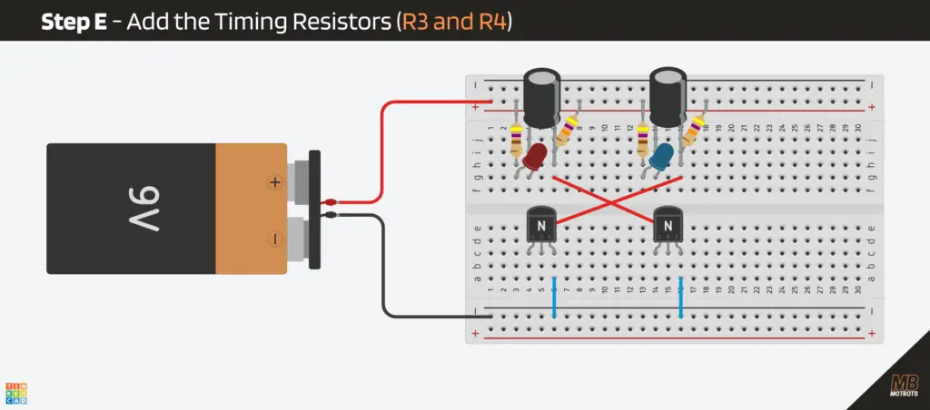
These resistors create the slow charging paths for the capacitors. The suggested values for the police-style blinking lights (red and blue) is 47kΩ. You can try around 33kΩ for a faster flash (10kΩ for high-speed chase flashing lights) or about 68kΩ for a slower flash.
I tried using both 47kΩ and 10kΩ values for the timing resistors. The following GIF image shows the difference in flash speed for each value for this circuit:
Step F – Collector Connections
To finish off our timing networks, we need to make the final connections to the collectors of each transistor.
- Take a jumper wire and place one end of it at the row where the positive (+) lead of capacitor (C1) is at. Take the other end of that same jumper wire and place it at the row where the collector (C) lead of transistor (Q1) is at (the orange wire in the image below).
- Take another jumper wire and place one end of it at the row where the positive (+) lead of capacitor (C2) is at. Take the other end of that same jumper wire and place it at the row where the collector (C) lead of transistor (Q2) is at (the blue wire in the image below).

The Outcome:
If everything goes right, and the crew of components are in proper positioning, our circuit should be flashing, once the power is connected. It’s like a call for backup was made for our crew. Uh-oh! The po-po!
🔍 What’s Actually Happening
Each component (or crew member) adds something to the group:
- Resistors (R1 and R2) control the intensity of the LEDs.
- The capacitors (C1 and C2) and resistors (R3 and R4) control the timing of the blink.
- The transistors (Q1 and Q2) handle the switching.
- Together, they create an oscillator — a fancy word for “thing that turns on and off repeatedly.”
This is literally the same concept behind computer clock signals, blinking indicators, and even sound generation. Wow, you just learned more than you bargained for, huh?
Here’s the sequence of events within our circuit (assuming Q1 turns on first), clearly and precisely:
- Q1 turns on first and the red LED turns on
- Q1 turning on makes its collector voltage drop
- That drop gets passed through a capacitor (C1) to Q2’s base
- Q2’s base gets pulled low, therefore Q2 turns off (blue LED off)
- With Q2 off, its capacitor (C1) slowly charges
- Q2’s base slowly climbs until it turns on
- When Q2 turns on, its collector drops
- That drop travels through the other capacitor (C2) to Q1’s base
- Q1’s base gets pulled low, therefore Q1 turns off (red LED off)
- Q1 gets kicked off, therefore the blue LED turns on
- Now the second capacitor (C2) slowly charges
- Q1 eventually turns back on
- The pattern repeats forever
👁️ Simulation for Visual Learners
I feel that I grasp a concept much better if I can visually see what is happening. The following simulator is a great way to see exactly what’s going on in our blinker circuit, as if we can see what the electrons are doing within the conductors. You can test and play with the exact same circuit using the interactive simulator below.
NOTE: Initially, the simulator is set to run the circuit at a very slow speed (we’re seeing it in the milliseconds time). To speed up things to see what happens in the circuit after a sufficient amount of time has passed (around 400ms or so for the initial setup), adjust the simulation and current speeds.
🔧 Try this circuit in the live simulator right here:
If the simulator is unresponsive, or you’re unable to view it here, then Run Simulator here.
⭐ Why This Example Is Cool
This tiny circuit demonstrates several fundamental electronic principles all at once:
- How resistors control current
- How capacitors store and release energy
- How transistors amplify or switch
- How components influence each other across different parts of a circuit
- How timing and behavior can emerge from simple parts
- How analog electronics can create patterns without any digital logic
This is electronics working as a team. In other words, a component on its own:
- A resistor can’t blink.
- An LED can’t blink.
- A capacitor can’t blink.
- A transistor can’t blink.
But together? They can make a rhythm, a pattern, and a little light show. It’s a great example of how components work together to create circuits.
Remember, each component uses its own “superpower,” and when combined can create and perform amazing things.
Video: How to Make an LED Blinker Circuit
🧩 Wrapping It Up: The Teamwork Makes the Dream Work
At first, our electronic components might have looked like random parts wired together in chaos. But now you know the secret: every resistor, capacitor, and transistor is playing its role in perfect rhythm. Together, we got them to create timing, control, and light.
The next time you power up a gadget, remember that it’s not magic inside — it’s teamwork. It’s a microscopic teamwork — running at the speed of electricity — and if you’ve made it this far, congratulations! You’re officially ready to start building your own circuits that blink, beep, and maybe even think.
So, grab your breadboard, power supply, and curiosity — and go make something awesome. Because now, you’re not just learning electronics, you’re learning how to give imagination a circuit to run on.
What’s Next?
Now that we’ve whet our appetite with the blinker circuit we made here, it’s time to move on to a more satiable circuit. No more of this kiddie stuff, next we’ll do things for real. In Part 4 of this 12 Part Super Series on Components, we’ll build a real circuit.
“What kind of circuit?”, you ask? I won’t spill the beans! That will have to be observed in Part 4: Building Your First Real Circuit.
Thank you for joining us on this journey of electronic components, thus far. We hope that you have enjoyed The LED Blinker Circuit. Let us know by giving a comment in the comments section below. Share the link to your friends and family. Let them know how much you’ve enjoyed the process of prototyping your own LED blinker circuit and learning how components work together.
Remember, keep at it and stay motivated.