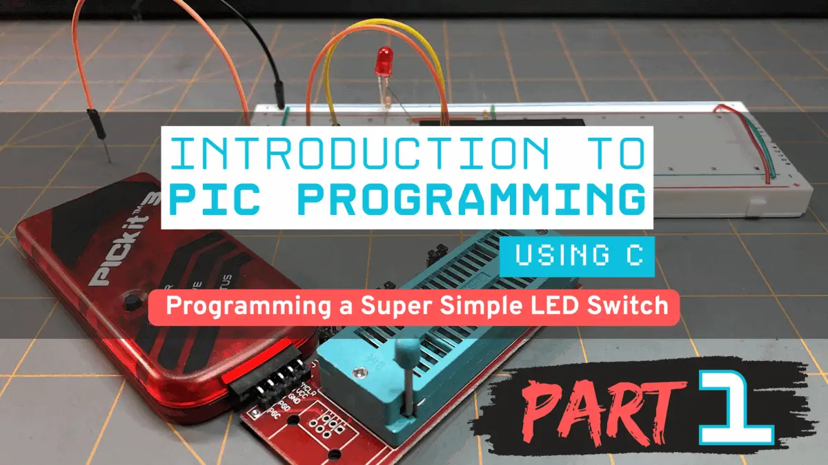
Introduction to PIC Programming Using C: Programming a Super Simple LED Switch – Part 1: The Preliminaries
| Project Name: | Introduction to PIC Programming Using C: Programming a Super Simple LED Switch – Part 1 |
| Project Description: | In Part 1, we discuss the basics of a PICkit, MPLAB, C, and other topics of interest. |
| Project Difficulty: | Easy to Moderate |
| Project Note: | Attempting this project requires some hardware and software to program a PIC microcontroller. You may observe what we’ll need here, and the parts list here. |
Introduction
Welcome! In the proceeding three part series, our goal is to learn how to program a PIC18F4525 microcontroller using the C programming language to control an LED with a couple of switches. It is my personal goal to help guide you to do this in a way that I learned from a terrific book I purchased some time ago of which you can observe for yourself at the Book Reference at the bottom of this page.
The following is intended to be an enhancement to such pedagogical material that sometimes leaves more to be desired for the reader. It is the intention of the following to add more input to the learning material that is currently available, or currently unavailable, in the market today on learning how to program a PIC microcontroller using the C programming language.
This is Part 1: The Preliminaries
This will be a three part series. This is Part 1. I’ve divided this content into three parts because there was so much information to share with you that having it all on one page may have been overwhelming. I don’t want you to feel overwhelmed.
This should be a fun and exciting topic, not an intimidating one.
In Part 1, we’ll discuss some basics, like what a PICkit is, and why we need a PICkit. We’ll talk about the PIC18F4525 microcontroller and Microchip’s MPLAB software. I’ll show you how to install the MPLAB software and how to set it up. We’ll also discuss things we’ll need to know in C, and other important topics we’ll need to know.
In Part 2, we’ll get into building the prototype circuit, and go over things like the parts and tools we’ll need. We’ll also discuss about power supplies, and get into what a flowchart is and the need to use one. We’ll go over the schematic of this super simple LED switch project, and we’ll even go over all the pins we’ll be using on the PIC18F4525.
In Part 3, we’ll finish our discussion by going over the code, line-by-line, and how it works. We’ll even go over some common errors when trying to connect the PICkit device to the MPLAB IPE. In Part 3, we’ll be finishing up the project as a whole. We’ll then test the circuit and hopefully at the end have a working circuit.
I’ll try to teach you in a coherent, methodical, detailed, step-by-step process – doing it this way helps to ensure that you are understanding where information is coming from and how to understand it. I try not to leave you in the dark. This is the way that I believe all things should be taught, and I hope that I can perform this job successfully for you!
So, let’s get to it and begin the process of learning to do this cool project! But first, let’s begin with a few things we’ll need for this project.
What We’ll Need
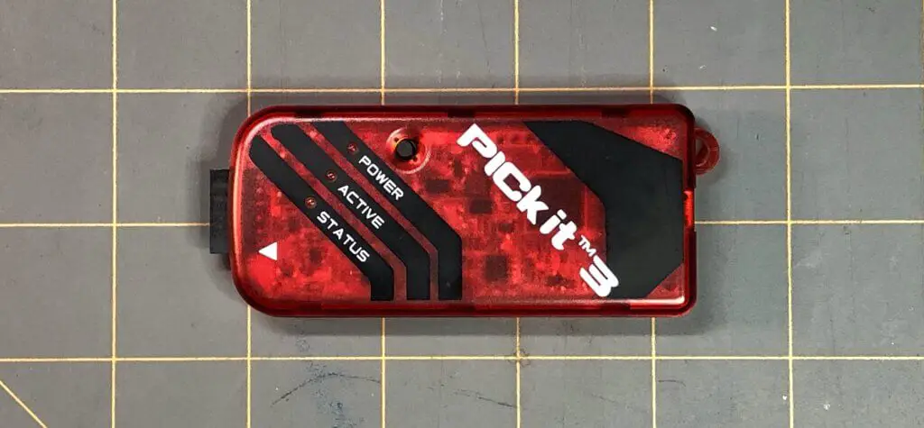
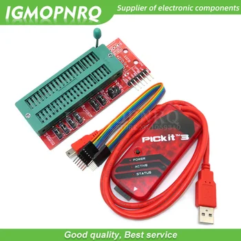
PICkit 3 In-Circuit Debugger/Programmer: We’ll learn about this later.
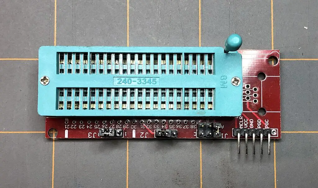
Universal Programmer Seat Board Adapter: We need this to easily make the connections of the pins of the PIC18F4525 microcontroller to the PICkit 3. This is one particular method to be able to communicate and transfer the compiled code we’ll write to the PIC microcontroller later. Using a universal programmer seat board adapter is easier than making connections between the two with jumper wires and a breadboard.
Microchips’s MPLAB X v6.15: We’ll need these set of software tools to be able to create our code and compile it for the microcontroller in an integrated development environment (IDE), and to upload our code through to the PICkit 3 programmer, to our PIC microcontroller, via an integrated programming environment (IPE).
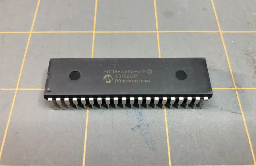
PIC18F4525 Microcontroller (MCU): We will be using this 8-bit microcontroller to get us started in the world of embedded systems and learning how to program PIC microcontrollers. We’ll learn more about the PIC18F4525, later.
There will be some other components we’ll need for this project that we’ll get to later in Part 2, but before we get into that, let’s go over some preliminaries of what we need to setup and what we need to know before we jump into this project.
Using the Ol’ PICkit 3 In-Circuit Debugger/Programmer

The PICkit 3 is a development tool created by Microchip Technology for programming and debugging PIC microcontrollers. It has been an essential tool for embedded systems developers who’ve worked with Microchip’s line of microcontrollers for several years now, but has now been essentially replaced by its successors; the PICkit 4, and PICkit 5 in-circuit debugger/programmers.
Although considered outdated, the PICkit 3 is still considered versatile, cost-effective, and is still widely used for debugging and programming tasks. The PICkit 3 is what we will be using for this particular discussion of programming a PIC microcontoller.
Know that most so called PICkit 3 programmers out there are copies or clones of the official PICkit 3. I will actually be using a cloned version for this project because that’s what I have. Although it’s not an official Microchip PICkit 3, it still functions and works as the real thing. It is fairly cheap and still relatively easy to acquire. If you do not have one, you can get one here.
If you’d like to use a newer version of one of the official Microchip PICkit in-circuit debugger/programmers, you can learn more about them here.
Why Do We Need a PICkit?
For this discussion, we will be using a PIC18F4525 microcontroller. The PIC18F4525 is a high-performance 8-bit microcontroller often used in embedded systems. If we want to use one in our project, we’d need to create some instructions for the PIC via code we’d write for it. Then, we’d need to somehow send that code to the microcontroller, so that it could use those instructions to perform the tasks we want it to for our project. This is where a PICkit comes in to help achieve that.
If you’ve ever used an Arduino Uno before, you may understand the importance of being able to code and compile your code to an Arduino’s onboard microcontroller, to then be able to perform the tasks you ask it to do.

The Arduino Uno is a development board that provides an easy-to-use platform for building electronic projects. It includes the ATmega328P microcontroller chip, along with other components like a USB connection, power jack, and a set of digital and analog pins that allows users to connect various input and output devices, such as an IR sensor, MP3 player, or LEDs, like we did when we used an Arduino Uno for the OwlBot project.
An Arduino has a complete development environment – all you have to do is plug a USB into it and connect it to a computer, use the Arduino integrated development environment (IDE), write your code in C/C++, then upload and compile your code to it. If your code is good to go (i.e. no errors), then you’re all set. That’s it!
However, the PIC microcontroller is a self-contained computer-on-a-chip. It is a standalone chip that contains a processor, memory, and peripherals on a single chip and has to be programmed with the use of a programmer, like a PICkit programmer. To program it, you need to use specific tools like the MPLAB IDE and IPE, and you need a physical programmer that transfers the binary code directly into the PIC’s memory — again, like the PICkit 3 programmer that we’ll be using for this discussion.
We need a PICkit to be able to program the PIC18F4525 with the code that we write in C in the MPLAB IDE. The PICkit acts as a bridge between language that humans can understand – that we write within the MPLAB IDE on our computer – and the binary encoded data in hexadecimal format that the PIC understands that’s compiled using the MPLAB IDE and written to the PIC’s memory using the MPLAB IPE.
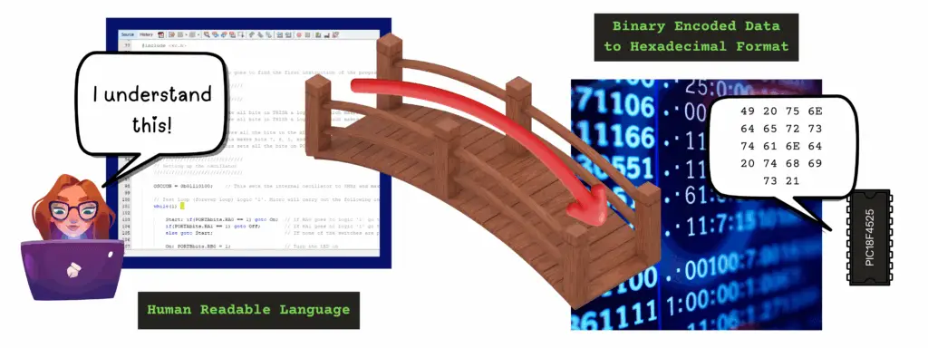
Copy/Paste: 49 20 75 6E 64 65 72 73 74 61 6E 64 20 74 68 69 73 21
The PIC18F4525 8-bit Microcontroller
As stated earlier, the Microchip PIC18F4525 is a high-performance 8-bit microcontroller often used in embedded systems – it’s a self-contained computer-on-a-chip. The PIC18F4525 is a standalone chip that contains a processor, memory, and peripherals on a single chip and has to be programmed with the use of a programmer.
The PIC18F4525 we’ll be using is a 40 pin PDIP (Plastic Dual Inline-Package) microcontroller that has a program memory size of 48KB, a RAM size of 3968, and data EEPROM of 1024 bytes. Its maximum operating voltage is 5.5V, and its minimum operating voltage is 2V.
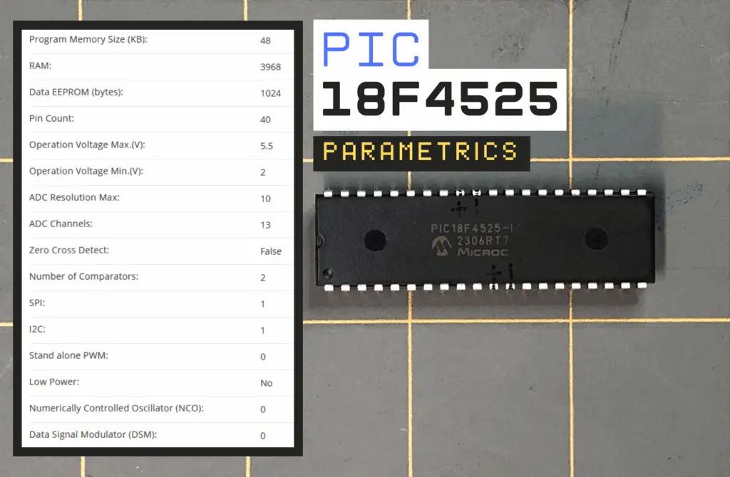
Some other features of the PIC18F4525 are as follows:
- Up to 10 MIPS (million of instructions per second) performance at 3V
- C compiler optimized RISC (reduced instruction set computer) architecture
- Internal oscillator support of 31kHz to 8MHz with 4xPLL (phase-lock loop)
- Watchdog Timer with separate RC (resistor-capacitor) oscillator
- Wide operating voltage range between 2.0V to 5.5V
- 10-bit ADC (analog-to-digital converter)
- Four Timer modules
- Up to 5 PWM (pulse-width modulation) outputs
It’s recommended that you download and observe the provided datasheet below for the PIC18F4525. Even if you don’t understand anything at this point, its good to glance over the first several pages of the datasheet to get a general understanding of the structure and information provided in a datasheet. YOU’LL NEED IT LATER, in Part 2.
Microchip PIC18F4525 Datasheet
Download the PIC18F4525 Datasheet
DON’T WORRY! We’ll go step-by-step on how to set up the microcontroller and use it for the specific tasks we’ll be performing for our project. We’ll even go into the why we’re doing things too. I’ll try to make it as simple as possible for you! DON’T BE INTIMIDATED!

But Isn’t the PICkit 3 Outdated?
Yes, the PICkit 3 is now outdated and is not recommended for new designs and no new device support will be added to it as of June 1, 2019. As per Microchip’s website, it’s recommended to see about their new designs, like the MPLAB PICKit 5. Microchip’s MPLAB PICKit 4 reached its EOL (End of Life) back in September of 2023.
All that being said, I already had a PICkit 3 on-hand that I purchased a few years ago, and that’s why I’m using it here for this project. It will work just fine for what we’re going to do, so if you’ve got one already, then you’re good to go! Don’t feel that you need to rush out and purchase a new PICkit — that won’t be necessary — at least at the time of writing this it won’t be.
A PICkit 3 can still be found and purchased if you don’t have one. They’re much cheaper than the updated versions, but if you choose to use an updated version, like the PICkit 5, then you should be able to still follow along just fine.
I recommend that if you plan to purchase the PICkit 5, to buy it directly from Microchip, if they’re available. If not, buying from somewhere else can sometimes cost you much more. I also recommend that you check out Microchip’s page on the MPLAB PICkit 5 In-Circuit Debugger to help you get started in using one.
MPLAB X v6.15
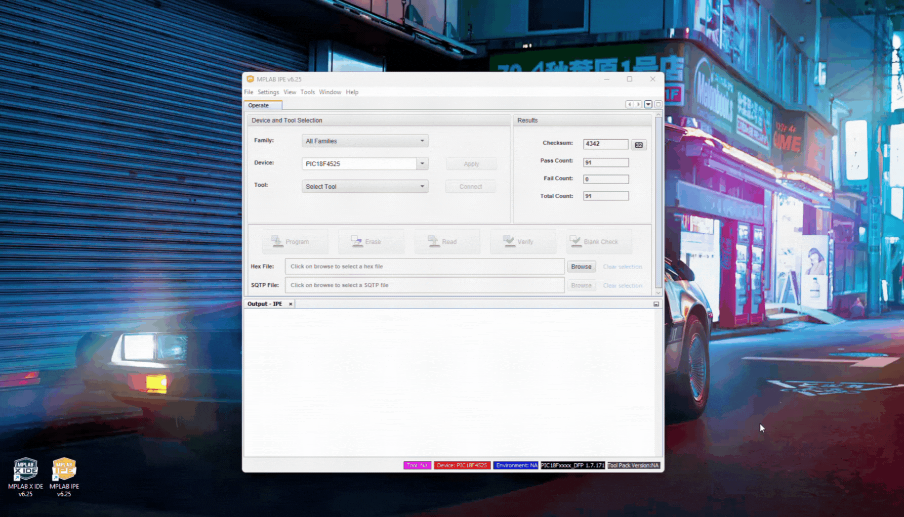
To be able to use the outdated PICkit 3, we’ll need the use an older version of Microchip’s MPLAB software tools. I tried to use the most recent version of MPLAB (v6.25) as of date (May 2025) and was unable to get MPLAB IPE v6.25 to recognize my PICkit 3 programmer when plugged into my computer with its USB cable.
Below is a GIF showing how the MPLAB IPE v6.25 would not recognize my PICkit 3, so it wouldn’t show up as a device to choose from the Select Tool menu.
MPLAB X v6.25 – PICkit 3 Not Recognized
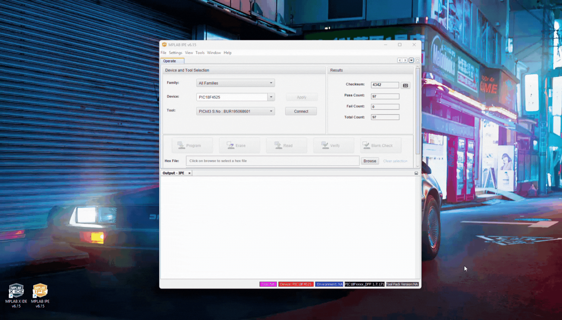
I will be using MPLAB X v6.15, as the software for both creating and compiling the code for the PIC microcontroller using the MPLAB IDE, and to upload the hex file to the PIC microcontroller using the MPLAB IPE.
I’ll be using Microchip’s MPLAB version 6.15, since this is the version I originally had installed on my personal computer. This version was able to recognize the PICkit 3 programmer when plugged into my computer with its USB cable, as can be seen in the GIF below. You can download MPLAB X v6.15 from Microchip’s website here.
MPLAB X v6.15 – PICkit 3 Recognized
I did not try version 6.20, so I do not know if that particular version will recognize the PICkit 3 programmer. You can give it a shot, if you’d like. Otherwise, I’d just stick with version 6.15, for now.
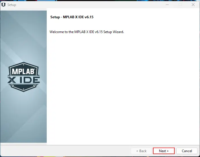
How to Download MPLAB X v6.15 (Windows)
- Download the MPLAB X v6.15, from Microchip’s website. Choose the version you need for your particular operating system (i.e. Windows, macOS, or Linux). In my case, I needed to download MPLAB X v6.15, for Windows.
- Once the MPLAB X installer downloads to your computer, run the application to begin the installation process. In my case, since I’m using Windows, I would need to double-click this application in my Downloads folder – the location where MPLAB X downloaded to on my computer.
- Click Yes to allow for the installation.
- A Setup window should open for MPLAB X IDE v6.15. Click Next.
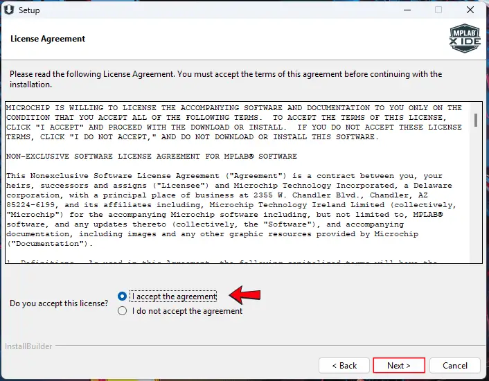
- You must accept the License Agreement to continue the setup process. Then, click Next.
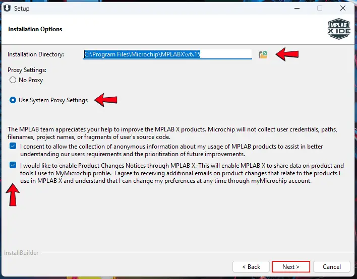
- You can leave the default Installation Directory as to where MPLAB X will be installed on your computer or change this location to your preference. Check the radio-button that states Use System Proxy Settings. You can leave the check boxes checked for consenting to allow the collection of anonymous information and enabling Product Changes Notices through MPLAB X, if you’d like. Then, click Next.
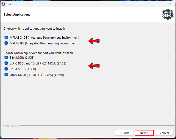
- In the Select Applications window, leave the MPLAB X IDE and MPLAB IPE boxes checked. We also need the 8 bit MCUs box left checked. I just left all boxes checked for this step, then I clicked Next.
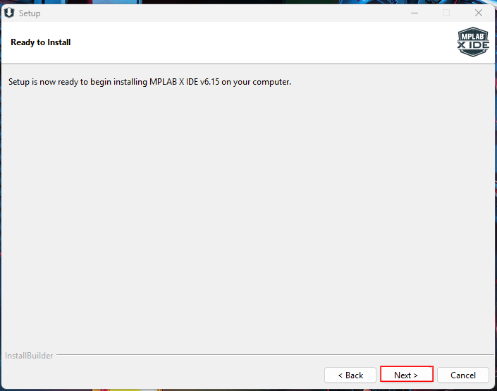
- The Setup window should now state that it’s now ready to begin installing MPLAB X v6.15 on your computer. Click Next to do so.
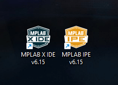
Once the software setup is complete, you should now have two new shortcuts on your desktop – one for MPLAB X IDE v6.15, and one for MPLAB IPE v6.15, as seen in the image below.
Okay, now that we have MPLAB setup and ready to go on our computer, let’s quickly go over some things about the C programming language first, before we start anything else. We’ll come back to MPLAB and the other stuff later, when everything all comes together.
What We Need to Know in C
The Preprocessor #include
#include is a preprocessing directive that runs before the actual compilation of code begins. It tells the compiler to use a standard or user-defined file in the program.
Basically, it’s just telling the compiler, “Hey, I want to include this file or library in my code here, to be able to use it later.” It’s almost always written at the beginning of the program and must include the hashtag or pound symbol (#) before the word include. For example, we could include the standard input/output library header in our code that supplies I/O functions that work with narrow characters, like this:
#include <stdio.h>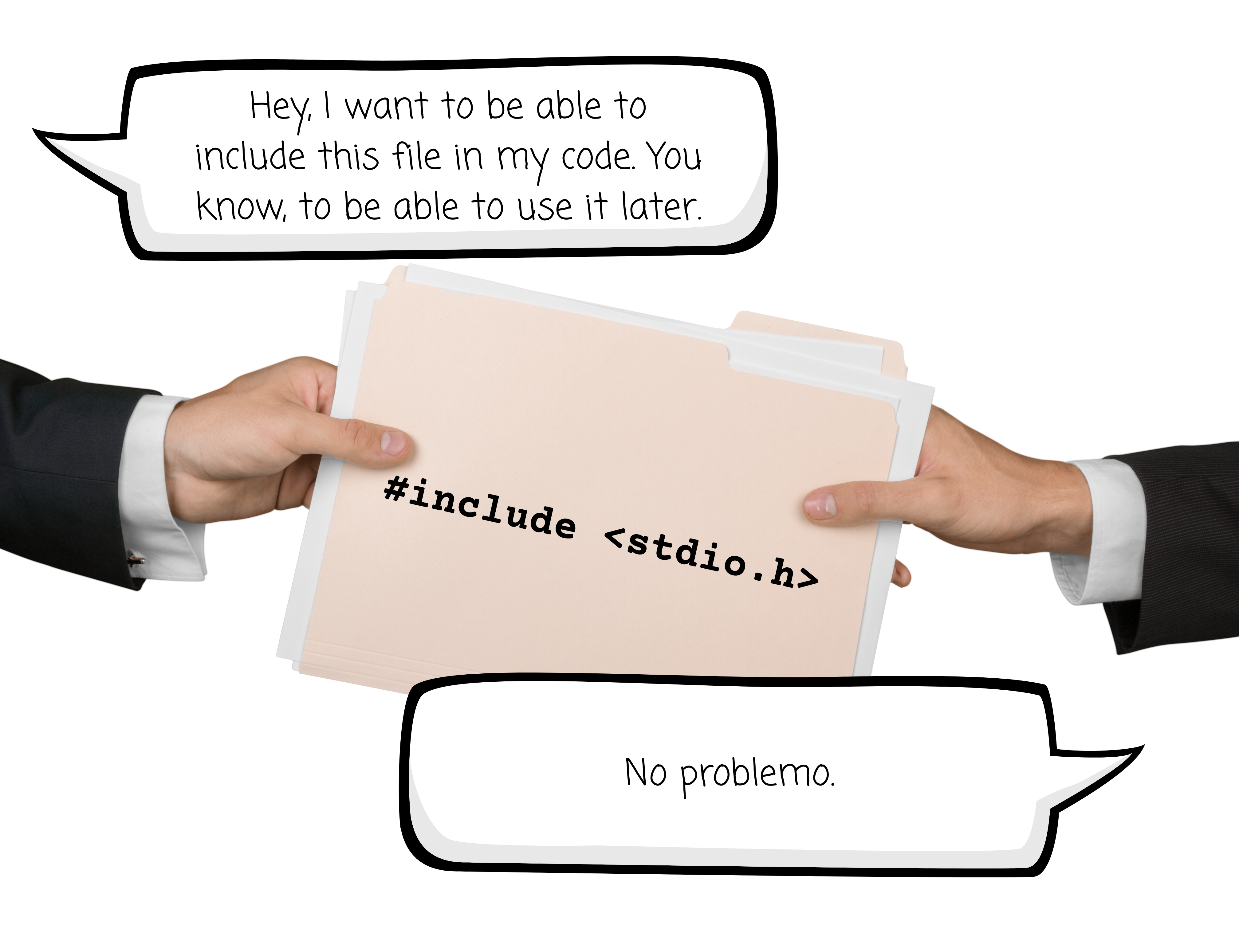
Main Function
The main function is a function named main that must be included in every C program. The main function is the entry point of a C program and is executed at the start of the program in a hosted environment, like an operating system.
We can think of main as being the main entrance or front door into our C code – without it, we have no way of getting in.

The syntax of the main function can be written in one of many forms. One such way is as follows:
void main(void) {
	// Code goes here between the open and closed curly-brackets
}In the above notation, the void return type means that the function does not return any information and the (void) in the parenthesis is a parameter that means that the function does not take any information either. The comment with the two forward slashes just lets us know that we write our code between the open and closed curly-brackets. The comment is ignored by the compiler.
While Loop
A while loop is a statement in a C program that executes a statement repeatedly until something causes the value of the expression to be equal to zero or false.
It’s like telling the program, “Hey, I’m gonna need you to keep doing this task for me while the statement I give you is true and stop doing the task when the statement is false. That would be great.”

For example, the following while loop will continue to loop through until the statement within it is false:
int counter = 0;

while(counter < 10) {
	counter++;  // increment counter by 1
}The while statement above evaluates the expression within the parenthesis, in this case a predefined variable within the code named counter. While the value of counter is less than 10, the statement is true and the loop will continue to execute.
Within the while loop is a statement that increments the value of counter by one each time the loop is executed. When counter is equal to 10 it makes the statement false and the code exits the while loop or the while loop ends.
We must be careful though, because it is easy to create an infinite loop. An infinite loop is an endless loop with no observable behavior in its statement or expression. An example of an endless loop is as follows:
int counter = 0;

while(counter < 10) {
	counter--;  // decrement counter by 1
}Similar to the previous while loop we observed, the statement above evaluates the expression within the parenthesis, in this case a predefined variable within the code named counter. While the value of counter is less than 10, the statement is true and the loop will continue to execute.
Notice, however, that inside the while loop is a statement that decreases the value of counter by one each time the loop is executed. If the value of counter is always being decremented by one, then the value of counter will never be greater than 10, therefore always keeping the statement true. This means that the while loop will continue indefinitely or most likely crash your program.
We may sometimes want a loop to continue “forever” and add one at the end of our program, like the following:
while(1) {
	// Want this code to never end
}For embedded systems, if we didn’t use an endless while loop at the end of a program, like the one above, the program would reach the end of its programming and terminate.
For an embedded system, like one that is meant to always determine if a button is pressed to either turn an LED on or off, would end prematurely if an endless while loop were not added to its programming. We would want to keep the program alive while listening to external interrupts, for example.
The argument of “1” inside the parenthesis in the while loop above, makes the statement true – actually it makes it always true. Therefore, the while loop above is an infinite loop, unless there is some external interrupt the while loop listens for within it.
The if-else Statement
The if-else statement is a conditional statement. It’s used in code only when some condition needs to be met for that part of the code to be executed. It’s like saying, “If the condition is true, then do this thing. Else, do that other thing.” For example:
// Heights given in inches
if(height > 0 && height < 60) {
	printf("You must be 60 inches or taller to ride the roller coaster.\n");
}
if(height < 0 || height > 84) {
  printf("You're kidding, right?\n");
}
else {
	printf("You are tall enough to ride this roller coaster!\n");
}The above statements first checks if the predefined variable height is greater than 0 and (&&) less than 60. If it is, then the print function prints to the terminal, “You must be 60 inches or taller to ride the roller coaster.”, and a new line (\n) is also printed to the terminal.
The next if statement checks for “out-of-bounds” values or “impossible” values for the ride. If the predefined variable height is less than 0 or (||) greater than 84, then the print function prints to the terminal, “You’re kidding, right?“, and a new line (\n). Else, then the print function prints to the terminal, “You are tall enough to ride this roller coaster!”, and a new line (\n).
The goto Statement and Labels
The goto statement in C allows the program to directly go to a certain point in the code, almost like jumping to some part of the code when needed to. You can think of the goto statement part of code as being like in a retro video game, where a side-scroll character finds a transport in the game to immediately go to another point in the level.

The goto statement gives the programmer more control over the program’s execution. Using a goto statement can be useful, at times, but is typically not recommended. Having goto statements in code, especially several of them, can make your code hard to read and understand, not only for yourself, but for others too. They’re also more difficult to maintain than using other ways to control the flow of code, like using your own functions and/or libraries.
An example of using a goto statement and labels is as follows:
while(1) {  // Endless loop
  Start: if(buttonOne == 1) goto On;  // If buttonOne is pressed (logic '1') go to the label On
  if(buttonTwo == 1) goto Off;        // If buttonTwo is pressed (logic '1') go to the label Off
  else goto Start;                    // If neither switch is pressed go to the label Start

  On: redLED = 1;                  	  // Turn the LED on
  goto Start;                         // Go to the label Start

  Off: redLED = 0;                 		// Turn the LED off
}We can see from the statements above that the code starts with an endless (infinite) while loop. For this particular application, an endless while loop is used for constantly listening for feedback from a user to press either of two momentary push-buttons to turn an LED on or off.
Such code is possibly used for an application that uses a microcontroller to control whether an LED is to be turned on or off, based on user input of pressing either of two separate momentary push-button switches.
A Start label begins the sequence of events within the while loop. If buttonOne is a logic ‘1’, or buttonOne is pressed, then a call to the On label is made within the loop to make the redLED a logic ‘1’, therefore, turning the red LED on.
If buttonTwo is pressed, or becomes a logic ‘1’, then a call to the Off label is made within the loop to make the redLED a logic ‘0’, therefore, turning the red LED off.
Now that we have some of the basics of C programming out of the way, let’s get to know about the hexadecimal number system. You may be asking at this point, “Huh?! Why are we learning about the hexadecimal number system?”
Good question. Well, to better understand some of the concepts of the code we’ll write later for our super simple LED switch project using a PIC microcontroller, we’ll want to familiarize ourselves with how we initialize certain registers we use from the PIC.
DON’T WORRY! We’ll get to what registers are and what kind we’ll use later on in our discussions. For now, let’s just continue on with the hexadecimal number system. Trust me, it’ll all make sense to you later… I hope.
Getting Familiar With the Hexadecimal Number System
When we start coding for the PIC18F4525, later on in our discussions, we’ll need to use what’s called special function registers (SFRs) for the PIC in our program. When initializing SFRs in code, we often use a hexadecimal format.
Sometimes we initialize these registers in code using a binary format. Sometimes we may need to make conversions between hexadecimal and binary, or from hexadecimal to decimal formats, or any other iteration between the formats.

Understanding Binary-to-Decimal Conversions
Before we try to understand the conversion from hexadecimal-to-decimal, let’s first understand the conversion from binary-to-decimal. The following is an example of an 8-bit binary number:
\begin{equation}
0b00001111 = 00001111
\end{equation}
Notice that the sequence of binary digits can be written in a couple different ways – one being with a “0b” prefix that tells us that this is a binary number, and the other being just the sequence of binary digits without the “0b” prefix.
The binary number system is a base 2 system. For the 8-bit example, those binary digits correspond to the order of the sum of powers of 2, in the following manner:
\begin{equation}
2^{7}2^{6}2^{5}2^{4}2^{3}2^{2}2^{1}2^{0}
\end{equation}
Notice how the powers of 2 start from right-to-left, starting with the first power of 2 having an exponent of zero. From right-to-left, each power of 2 has an exponent, in sequence, from 0 to 7, fulfilling all 8 bits of the powers of 2.
Now, if we correspond the ‘1s’ as the bits being active or on, and the ‘0s’ as the bits being deactivated or off, and associate each value of the binary number with its corresponding representation of powers of 2, then we can perform the following step:
\begin{equation}
\quad0000\quad1111
\end{equation}
\begin{equation}
\quad\Downarrow\quad\Downarrow
\end{equation}
\begin{equation}
\quad2^{7}2^{6}2^{5}2^{4}\quad2^{3}2^{2}2^{1}2^{0}
\end{equation}
\begin{equation}
\quad\Downarrow\quad\Downarrow
\end{equation}
\begin{equation}
\text{Off}\ \text{Off}\ \text{Off}\ \text{Off}\quad\text{On}\ \text{On}\ \text{On}\ \text{On}\
\end{equation}
\begin{equation}
\quad\Downarrow\quad\Downarrow
\end{equation}
\begin{equation}
\quad0000\quad2^{3}2^{2}2^{1}2^{0}
\end{equation}
Now, let’s perform the operation for the values of the powers of 2 and separate each value by parenthesis. Note that the parenthesis here will NOT mean to multiply. Here, we’re just using them to clearly separate each value. In the later steps, we’ll sum the values to obtain the converted decimal value.
\begin{equation}
\quad0000\quad2^{3}2^{2}2^{1}2^{0}
\end{equation}
\begin{equation}
\quad\Downarrow\quad\Downarrow
\end{equation}
\begin{equation}
\quad(0)(0)(0)(0)\quad(8)(4)(2)(1)
\end{equation}
Now, take the sum of the values to obtain the converted decimal value:
\begin{equation}
\quad(0)(0)(0)(0)\quad(8)(4)(2)(1)
\end{equation}
\begin{equation}
\quad\Downarrow\quad\Downarrow
\end{equation}
\begin{equation}
0+0+0+0\ +\ 8+4+2+1
\end{equation}
\begin{equation}
\Rightarrow8+4+2+1 = \boxed{15}
\end{equation}
So, the binary number 00001111, when converted to decimal format, is 15.
\begin{equation}
\boxed{00001111\quad\equiv\quad15}
\end{equation}

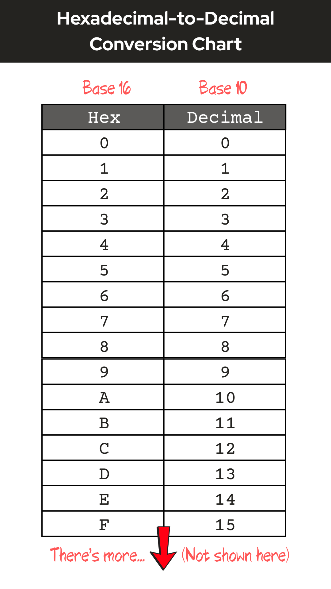
Understanding Hexadecimal-to-Decimal Conversions
The hexadecimal number system is a base 16 system. These numbers can be represented as powers of 16. For example, if we had a hexadecimal number represented as 0x0F, then we could determine its equivalent decimal number (base 10) as follows:
\begin{equation}
0x0F = (0F)_{16}
\end{equation}
\begin{equation}
(0F)_{16} = (0*16^{1})+(F*16^{0})
\end{equation}
Notice that the hexadecimal number is represented in two different ways – one with a “0x” prefix, denoting that this is a hexadecimal number, and the other written within parenthesis with a subscript value of 16, also denoting that it is a hexadecimal number.
Referring to the hexadecimal-to-decimal conversion chart below, 0 corresponds to the decimal value 0, and F corresponds to the decimal value 15. Therefore,
\begin{equation}
(0F)_{16} = (0*16^{1})+(F*16^{0}) = (0*16^{1})+(15*16^{0})
\end{equation}
\begin{equation}
(0*16^{1})+(15*16^{0}) = (0*16)+(15*1) = (0)+(15) = \boxed{15}
\end{equation}
So, the hexadecimal number 0x0F, when converted to decimal format, is 15.
\begin{equation}
\boxed{0x0F\quad\equiv\quad15}
\end{equation}
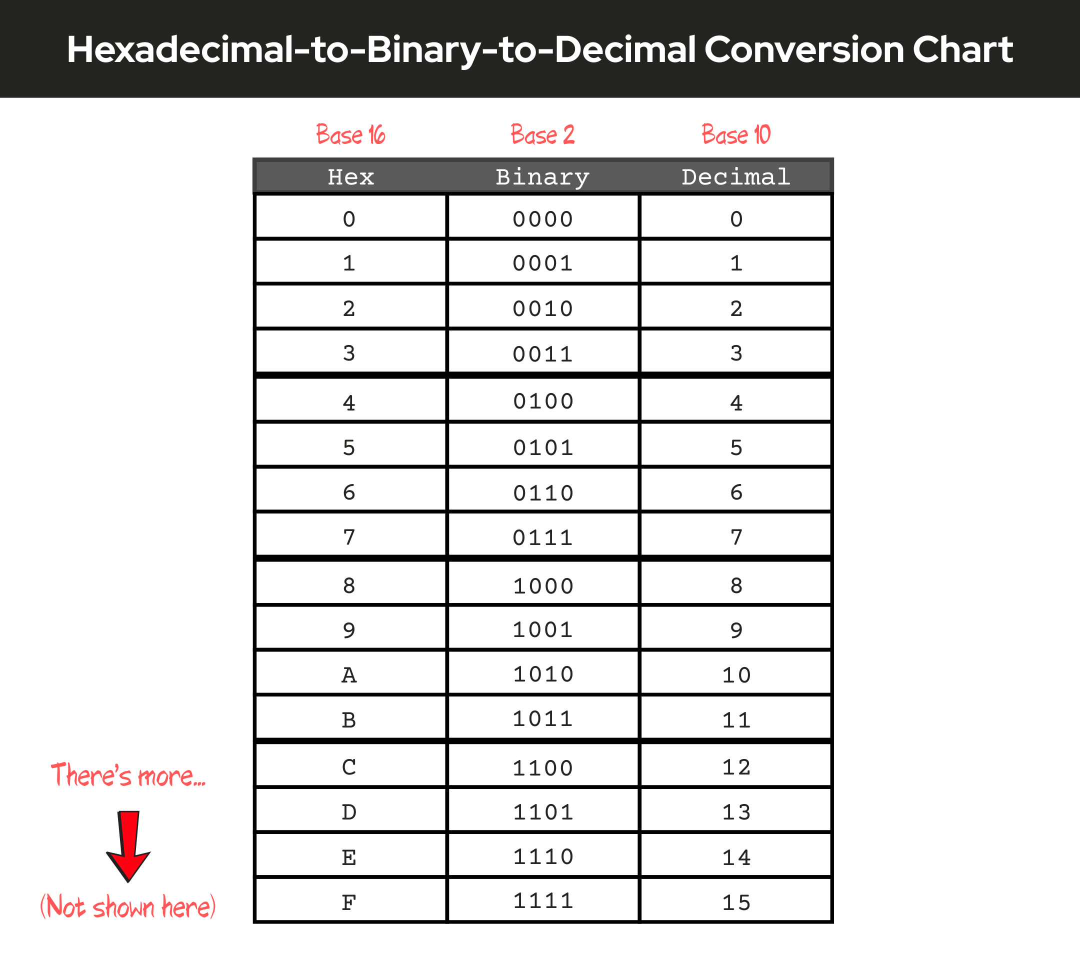
Understanding Hexadecimal-to-Binary-to-Decimal Conversions
Each hexadecimal digit represents four binary digits and each of those are represented as a power of 2. For example, let’s observe the binary value of all 1s, 11111111:
\begin{equation}
11111111\quad\rightarrow\quad1111\quad1111
\end{equation}
- Referring to an 8-digit binary number and to the first four rightmost binary digits containing the value 1111, and working our way from right-to-left, the rightmost digit is represented as 20, which is equivalent to 1.
- The second rightmost digit is represented as 21, which is equivalent to 2.
- The third digit from the right is represented as 22, which is equivalent to 4,
- and the fourth digit from the right is represented as 23, which is equivalent to 8.
- Now, referring to the last four leftmost binary digits containing the value 1111, again working our way from right-to-left, the rightmost digit is represented as 24, which is equivalent to 16.
- The next digit in line is represented as 25, which is equivalent to 32.
- The next leftmost digit in line is represented as 26, which is equivalent to 64.
- Finally, the leftmost digit in line is represented as 27, which is equivalent to 128.
\begin{equation}
\quad1111\quad1111
\end{equation}
\begin{equation}
\quad\Downarrow\quad\Downarrow
\end{equation}
\begin{equation}
\quad2^{7}2^{6}2^{5}2^{4}\quad2^{3}2^{2}2^{1}2^{0}
\end{equation}
\begin{equation}
\quad\Downarrow\quad\Downarrow
\end{equation}
\begin{equation}
(128)(64)(32)(16)\quad(8)(4)(2)(1)
\end{equation}
Recall that binary digits correspond to the order of the sum of powers of 2, starting in order of the value of their exponent from right-to-left. An 8-bit binary number’s decimal value can only range from 0 to 255. The reason for this is that if the 8-bit binary number were all zeros, then the sum of the powers of 2 would be equal to 0, and if the 8-bit binary number were all ones, then the sum of the powers of 2 would be equal to 255, as shown below:
8-Bit Binary Number as All Zeros
\begin{equation}
\quad0000\quad0000
\end{equation}
\begin{equation}
\quad\Downarrow\quad\Downarrow
\end{equation}
\begin{equation}
\quad2^{7}2^{6}2^{5}2^{4}\quad2^{3}2^{2}2^{1}2^{0}
\end{equation}
\begin{equation}
\quad\Downarrow\quad\Downarrow
\end{equation}
\begin{equation}
\text{Off}\ \text{Off}\ \text{Off}\ \text{Off}\quad\text{Off}\ \text{Off}\ \text{Off}\ \text{Off}
\end{equation}
\begin{equation}
\quad\Downarrow\quad\Downarrow
\end{equation}
\begin{equation}
(0)(0)(0)(0)\quad(0)(0)(0)(0)
\end{equation}
\begin{equation}
\quad\Downarrow\quad\Downarrow
\end{equation}
\begin{equation}
0+0+0+0+0+0+0+0 = \boxed{0}
\end{equation}
8-Bit Binary Number as All Ones
\begin{equation}
\quad1111\quad1111
\end{equation}
\begin{equation}
\quad\Downarrow\quad\Downarrow
\end{equation}
\begin{equation}
\quad2^{7}2^{6}2^{5}2^{4}\quad2^{3}2^{2}2^{1}2^{0}
\end{equation}
\begin{equation}
\quad\Downarrow\quad\Downarrow
\end{equation}
\begin{equation}
\text{On}\ \text{On}\ \text{On}\ \text{On}\quad\text{On}\ \text{On}\ \text{On}\ \text{On}
\end{equation}
\begin{equation}
\quad\Downarrow\quad\Downarrow
\end{equation}
\begin{equation}
(128)(64)(32)(16)\quad(8)(4)(2)(1)
\end{equation}
\begin{equation}
\quad\Downarrow\quad\Downarrow
\end{equation}
\begin{equation}
128+64+32+16+8+4+2+1 = \boxed{255}
\end{equation}
A hexadecimal number is represented by the following 16 values:
\begin{equation}
0,\ 1,\ 2,\ 3,\ 4,\ 5,\ 6,\ 7,\ 8,\ 9,\ A,\ B,\ C,\ D,\ E,\ F
\end{equation}
Each digit of a hexadecimal number counts a power of 16.
If we had the hexadecimal number represented as 0x0F – only looking at the “0F” part, we see that the F is the 15th value of the sequence of numbers, from 1 to F. The value 15, in binary is represented as:
\begin{equation}
1111
\end{equation}
The value of the zero in the “0F” part we’re looking at is just 0. So, we know that in binary, the value of 0 is represented as:
\begin{equation}
0000
\end{equation}
Putting our binary values in order with our hexadecimal value, we get the conversion from hexadecimal-to-binary:
\begin{equation}
\boxed{0x0F\quad\equiv\quad00001111}
\end{equation}
To go from binary-to-decimal, we just use the same process as we did before, when we correspond the ‘1s’ as the bits being active or on, and the ‘0s’ as the bits being deactivated or off, and associate each value of the binary number with its corresponding representation of powers of 2:
\begin{equation}
\quad0000\quad1111
\end{equation}
\begin{equation}
\quad\Downarrow\quad\Downarrow
\end{equation}
\begin{equation}
\quad2^{7}2^{6}2^{5}2^{4}\quad2^{3}2^{2}2^{1}2^{0}
\end{equation}
\begin{equation}
\quad\Downarrow\quad\Downarrow
\end{equation}
\begin{equation}
\text{Off}\ \text{Off}\ \text{Off}\ \text{Off}\quad\text{On}\ \text{On}\ \text{On}\ \text{On}
\end{equation}
\begin{equation}
\quad\Downarrow\quad\Downarrow
\end{equation}
\begin{equation}
(0)(0)(0)(0)\quad(8)(4)(2)(1)
\end{equation}
Note that the parenthesis here does NOT mean to multiply. We will take the sum of the values to obtain the converted decimal value:
\begin{equation}
(0)(0)(0)(0)\quad(8)(4)(2)(1)
\end{equation}
\begin{equation}
\quad\Downarrow\quad\Downarrow
\end{equation}
\begin{equation}
0+0+0+0+8+4+2+1 = \boxed{15}
\end{equation}
So, the binary number 00001111, when converted to decimal format, is 15.
\begin{equation}
\boxed{00001111\quad\equiv\quad15}
\end{equation}
So, going from hexadecimal-to-binary-to-decimal, we get the following equivalency:
\begin{equation}
\boxed{0x0F\quad\equiv\quad00001111\quad\equiv\quad15}
\end{equation}
Conclusion
Okay, now that we have some of the preliminaries out of the way, we can proceed on to the fun stuff! In Part 2 of this Introduction to PIC Programming Using C: Programming a Super Simple LED Switch, we’ll actually get to start building our circuit on the breadboard!
Part 2 will start off with providing you the entire parts and tools list for this project, and move on to topics like power supplies, flowcharts and why we need them, we’ll go over the schematic for this project, along with going over the details of the pins we’ll be using on the PIC18F4525.
I hope that you’ve found the information here useful and really hope that this content has been helpful for you. I know that these preliminary steps of the process may seem tedious and boring to some, but as with all things new to learn, we must trudge through the tough stuff, so that we may gain a better understanding and experience on the subject matter. We don’t want to be left in the dark on things.
If you’ve found this information useful, please leave us a comment below. We’d love to hear from you. Help spread the word about Motbots, so that we may help others with similar interests as you in electronics and robotics. Thanks for your time here! We’ll see you in Part 2! Remember to keep at it and stay motivated.

Book Reference
A lot of thanks needs to be given to Hubert Henry Ward and his book titled C Programming for the PIC Microcontroller. The knowledge that he’s shared in his book has not only helped me in my understanding of PIC programming in C, but I’m sure in many others as well.
Mr. Ward’s book starts you in the basics of what you need to know, gradually building your understanding of C programming, PIC microcontrollers, and the MPLABX software. His book will walk you through, step-by-step, during the learning process and on to applying what you’ve learned by performing easy-to-follow projects, often providing pictures within the pages.
In his book, you’ll participate in PIC projects like an LED traffic light, creating a volt meter and use an LCD screen to view voltage outputs. You’ll even delve deeper into some more useful code using the C programming language for the PIC microcontroller.
I highly encourage you to check out Mr. Ward’s book, C Programming for the PIC Microcontroller, so that you too can learn about PIC programming using C.

