Microcontroller 101: A Brief on GPIO, Timers, ADC, PWM, and Interrupts (ATmega328P)
Introduction
In Part 5, of the Circuit Component Super Series, we introduced microcontrollers as the control layer — the decision-making core that transforms simple circuits into intelligent systems. Now it’s time to go deeper and understand how it works internally.
This article breaks down the fundamental building blocks you’ll encounter in nearly every microcontroller project:
- GPIO basics
- Timers and delays
- ADC (Analog-to-Digital Conversion)
- PWM (Pulse-Width Modulation)
- Interrupts
- Debouncing buttons
These aren’t advanced features, they’re the foundation of embedded systems — master these, and you can control almost anything.
Welcome to the Embedded Intelligence Series
Welcome to the Embedded Intelligence Series, a sub-series to Part 5, of the Circuit Component Super Series, titled “From Circuits to Smart Systems: Introducing Microcontrollers”.
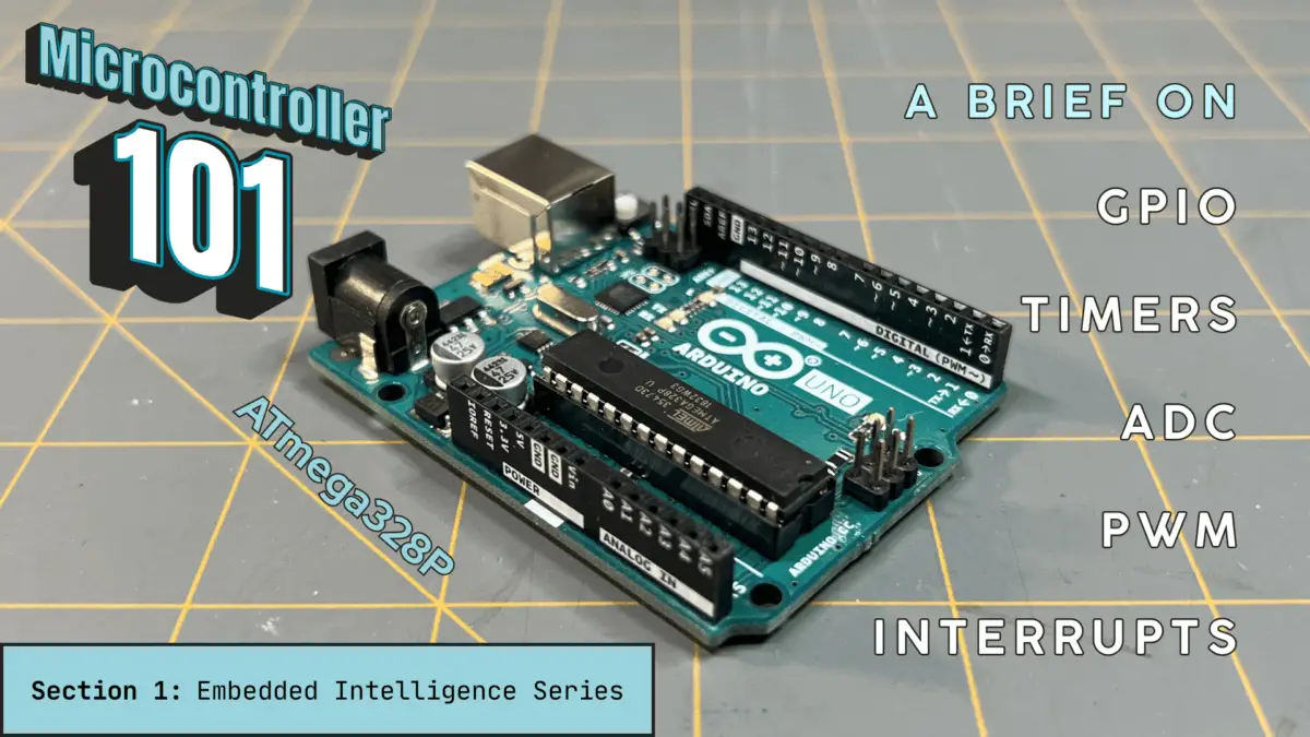
This is the first section of the Embedded Intelligence Series — Microcontroller 101: GPIO, Timers, ADC, PWM, and Interrupts (ATmega328P), where the title and the introduction above explains what it’s about.
The Embedded Intelligence Series will provide you a continuation on the microcontroller — further advancing your, knowledge, know-how, and skill on the microcontroller. This series and its sections will be structured as follows:
- Section 1: Microcontroller 101 (ATmega328P) (⬅️ YOU ARE HERE)
- Section 2: Microcontroller 101 (PIC18F4525)
- Section 3: Real-World Interfacing
- Section 4: Smart Behavior
- Section 5: Next Steps
- Section 6: Arduino LED Blinker (Project)
- Section 7: PIC Temperature-Controlled Fan (Project)
This series expands on the foundational concepts of microcontrollers and takes you deeper into how they function internally — and more importantly, how to configure and program them to bring your designs to life.
Before we get started, let’s have a look at the Arduino Uno microcontroller.
The Arduino Uno (ATmega328P)

The Arduino Uno is a development board developed to make prototyping your electronic ideas into reality more easily. It’s simplicity allows for people new to the world of making with electronics create things without needing tons of formal training.
This development board is based on the ATmega328P microcontroller, and programming it is easy to do in the Arduino IDE, once you get the hang of the coding rules. You can download the newest release of the Arduino IDE here.
We won’t be doing an in depth setup of the Arduino IDE here, or go over the programming language syntax during this project.
If you need help on uploading and taking care of certain errors you may encounter, please visit our OwlBot project page for Part 1, where we go over Compiling and Uploading the Code to Arduino and Possible Errors and How to Fix Them, there on that page.

If you need to know how to setup your computer for the Arduino IDE, then you can visit the Arduino web-page on how to Download and install the Arduino IDE here. Below, I’ve provided some recommended video content to help you get started using the Arduino:
- GreatScott!: Arduino Basics 101: Hardware Overview, Fundamental Code Commands
- Programming Electronics Academy: Arduino MASTERCLASS | Full Programming Workshop in 90 Minutes!
- Paul McWhorter (recommended): New Arduino Tutorials (playlist)
In the following, we’ll go over some of the pins of the Arduino Uno, and of course the topics of interest in this particular article. So, let’s get started with the basics — GPIO basics, next.
GPIO Basics (General Purpose Input/Output)
GPIO pins are the most basic way a microcontroller connects to the outside world. They’re versatile digital signal pins that can be configured to receive input signals or send output signals, depending on what your needs are:
- Input – Reads voltage level
- Output – Drives voltage level
The input mode is used to detect button presses, read digital sensors, or even monitor switches. Pins must not be left floating though, so that’s why we use pull-up resistors or pull-down resistors to help alleviate this.

The output mode is used to drive LEDs, trigger transistors, or enable motor drivers, for example. It’s important to note though, that GPIO pins cannot drive high current loads directly. External components, like MOSFETs are still required.
Again, GPIO (General Purpose Input/Output) pins are the primary way a microcontroller interacts with the outside world, but not all GPIO implementations are the same.
In this section and the next, we’ll be comparing two microcontrollers, the Arduino Uno and the Microchip PIC18F4525, and learn their differences. Here, in Section 1, we’ll go over the Arduino Uno, then in Section 2, we’ll go over the Microchip PIC18F4525.
GPIO Pins: Arduino Uno (ATmega328P)
Total GPIO Pins
The Arduino Uno R3 provides 14 digital I/O pins (pins D0 – D13) and 6 analog input pins (pins A0 – A5). Although A0–A5 are primarily ADC inputs, they can also be used as digital I/O. In total, the Uno offers up to 20 usable GPIO pins.
Voltage Levels
The voltage levels of the Arduino Uno are as follows:
- Operating Voltage: 5V
- Logic HIGH is typically considered HIGH when above ~0.6 × VCC.
- Logic LOW is below ~0.3 × VCC.
On the Arduino Uno, VCC refers to the 5-volt supply voltage used to power the microcontroller and other onboard components. This voltage is typically provided by the board’s voltage regulator or USB connection and is available on the 5V pin for powering external devices.
⚠️ The ATmega328P is not tolerant of voltages above VCC. Applying more than 5V to an I/O pin can permanently damage the chip.
Current Capabilities
The Uno’s current capabilities per pin are:
- Recommended Max: 20mA is the practical safe design limit.
- Absolute Max: 40mA is absolute maximum rating (do not design at this level).
The total current across all I/O pins combined should not exceed approximately 200 mA. This means that you can drive an LED directly, with a resistor, but you cannot drive motors or relays directly.
Motors, relays, and other inductive loads require external driver circuitry such as a transistor, MOSFET, or driver module.

Pin Configuration
The Arduino abstracts hardware configuration using code as follows:
pinMode(pin, INPUT);
pinMode(pin, OUTPUT);
pinMode(pin, INPUT_PULLUP);Behind the scenes, Arduino configures the DDRx and PORTx registers to set pin direction and enable pull-up resistors. The PINx register is used when reading input states. Arduino hides this register-level complexity, making configuration beginner-friendly.
| Register | Purpose |
| DDRx (Data Direction Register) | Controls whether a pin is an input (0) or output (1). Example: setting a bit to 1 makes that pin an output. |
| PORTx (Port Data Register) | If the pin is an output, writing 1 sets the pin HIGH and 0 sets it LOW. If the pin is an input, writing 1 enables the internal pull-up resistor. |
| PINx (Port Input Register) | Used to read the current logic level present on a pin configured as an input. Returns 1 for HIGH and 0 for LOW. |
The ATmega328P organizes GPIO pins into ports (PORTB, PORTC, and PORTD). The “x” becomes B, C, or D depending on the port.
🤔 What does “abstract” mean for Arduino?
In the context of Arduino programming, “abstract” means that the low-level hardware details are hidden behind simple function calls. For example, when you call pinMode(), you don’t directly manipulate hardware registers like DDRx or PORTx. Instead, the Arduino core handles that configuration for you.
This abstraction allows the same code to run across different boards (Uno, Mega, Nano, etc.) without the programmer needing to know the exact register layout of each microcontroller. As a result, beginners can write readable, portable code while the underlying hardware complexity remains hidden.
Special GPIO Capabilities
Some of the Arduino’s digital pins support:
- Pulse-Width Modulation(PWM): pins D3, D5, D6, D9, D10, and D11
- External Interrupts: pins D2 and D3
- Serial Peripheral Interface (SPI): pins D10 – D13
- Inter-Integrated Circuit (I2C): pins A4 (SDA) and A5 (SCL)
- Universal Asynchronous Receiver-Transmitter (UART): pins D0 (RX) and D1 (TX)
Many GPIO pins are multiplexed, meaning a single physical pin can serve multiple hardware functions (e.g., digital I/O, PWM, SPI, or I2C), depending on how it is configured.
Timers and Delays
Microcontrollers execute millions of instructions per second, but embedded systems must interact with real-world time. For example, a system may need to:
- Blink an LED every second
- Generate PWM signals
- Measure pulse width
- Schedule events
- Debounce buttons
- Run multitasking loops
Timers convert raw clock cycles into predictable, measurable time intervals. Without timers, time-dependent behavior would either require blocking delays or result in imprecise software timing.
Next, we examine the timers and delays for the Arduino Uno (ATmega328P).
Arduino Uno (ATmega328P) Timers and Delays
The ATmega328P includes three hardware timers:
| Timer | Resolution | Type |
| Timer0 | 8-bit (0–255) | Used internally by Arduino for millis(), micros(), and delay(). Also supports PWM (pins D5, D6). Not typically modified in beginner projects. |
| Timer1 | 16-bit (0–65,535) | High-precision timer. Ideal for accurate timing intervals, input capture, servo control, and advanced PWM (pins D9, D10). Best choice for precise interrupt-based scheduling. |
| Timer2 | 8-bit (0–255) | Independent 8-bit timer often used for PWM (pins D3, D11) and tone generation. Can run asynchronously with an external clock source. Useful when Timer0 and Timer1 are already in use. |
Clock Source
The Arduino Uno R3 runs at 16 MHz or 16 million clock cycles per second. Timers divide this using a prescaler.
Prescalers
Prescalers reduce the input clock frequency. For example, for Timer1, its available prescalers are:
- 1
- 8
- 64
- 256
- 1024
If using prescaler 64, you divide the system clock frequency by the prescaler value:
\begin{equation}
\frac{\text{16 MHz}}{64} = \text{250,000 Hz}
\end{equation}
Remember, the unit of Hz (Hertz) is an inverse second (Hz = 1/s). To obtain each timer tick, you’d simply take the inverse of the figure above:
\begin{equation}
\frac{1}{\text{250,000 Hz}} = \frac{1}{\text{250,000}\text{[}\frac{1}{s}\text{]}} = \text{0.000004s} = 4\mu\text{s}
\end{equation}
This is how we scale time into usable increments.

Software Delays
To create a delay, Arduino provides the following in code:
delay(ms);
delayMicroseconds(us);
millis();
micros();delay() blocks execution, and both millis() and micros() rely on Timer0 internally.
That means that if you reconfigure Timer0 manually, millis() and delay() break. This is important when doing advanced timing work.
Timer1 (16-bit Precision Example)
Timer1 is commonly used for precise timing, servo control, input capture, and high-resolution delays. As seen in the table above, Timer1 has a resolution of 16-bits, so its maximum count is:
\begin{equation}
2^{16} = \text{65,536}
\end{equation}
With prescaler 64, to find the maximum interval, we’d take the product of this prescaler and the timer tick we calculated above:
\begin{equation}
\text{65,536}\,\text{x}\,4\mu\text{s} = \text{262,144}\mu\text{s}\approx 262.1\text{ms}
\end{equation}
Longer delays require overflow counting.
🤔 What is overflow counting?
Overflow counting refers to allowing a hardware timer to count up to its maximum value. When the timer reaches that limit, it resets back to zero — an event known as an overflow — and can generate an interrupt.
This feature is especially useful in applications such as pulse counting or frequency measurement. By handling the overflow event inside an interrupt service routine (ISR), you can keep track of additional counts beyond the timer’s built-in limit and maintain accurate measurements over longer periods of time.
Timer Modes
Timers support multiple modes:
- Normal (overflow mode)
- CTC (Clear Timer on Compare)
- Fast PWM
- Phase Correct PWM
An example CTC use would be when a timer resets automatically when reaching a compare value. This would be how you’d generate exact periodic interrupts.
Interrupt-Based Timing (Recommended Method)
Instead of blocking with delay(), you can use interrupts. For example:
ISR(TIMER1_COMPA_vect) {
    toggleLED();
}An ISR (Interrupt Service Routine) is a special function in Arduino that executes in response to an interrupt signal. This enables non-blocking scheduling and cooperative multitasking.
ADC (Analog-to-Digital Conversion)
An ADC (Analog-to-Digital Converter) converts a continuously varying voltage into a digital number that firmware can process.
Microcontrollers cannot measure “temperature” or “light.” They measure voltage. The ADC translates that voltage into a binary value.
Arduino Uno (ATmega328P) ADC
Resolution
The ATmega328P ADC has a 10-bit resolution. That means that the MCU has:
\begin{equation}
2^{10} = 1024\;\text{possible values}
\end{equation}
What this means is that the digital output range is from 0 to 1023. Note that when including 0 (zero), one-thousand twenty four possible values is from 0 to 1023.
Reference Voltage (Vref)
The ADC compares input voltage to a reference voltage. By default, on the Arduino Uno, Vref is:
\begin{equation}
V_{\text{ref}} = 5\text{V}
\end{equation}
So, what that means is:
\begin{equation}
0\text{V}\;\equiv\;0
\end{equation}
\begin{equation}
5\text{V}\;\equiv\;1023
\end{equation}
Each step equals:
\begin{equation}
\frac{5\text{V}}{1023}\approx4.88\text{mV per step}
\end{equation}
This is the smallest measurable voltage change that the ADC can detect.
analogRead()
Arduino provides an analogRead() function that, behind the scenes:
- Selects the ADC channel
- Configures prescaler
- Starts conversion
- Waits for completion
- Returns 10-bit result
All of this is abstracted. In code, it looks like:
int value = analogRead(A0);Where the argument A0, is the analog pin A0, on the Arduino.
ADC Clock and Prescaler
The ATmega328P ADC works best between 50 kHz – 200 kHz, for the ADC clock. Since Arduino runs at 16 MHz, the prescaler is typically set to 128:
\begin{equation}
\frac{16\text{MHz}}{128} = 125\text{kHz}
\end{equation}
Which is a perfect ADC operating range.
Conversion Time
The ADC conversion time takes approximately 13 ADC clock cycles. At 125 kHz, the ADC conversion time would be approximately:
\begin{equation}
\frac{13}{125\text{kHz}} = \frac{13}{\text{125,000Hz}} = \frac{13}{\text{125,000}[\frac{1}{s}]}\approx104\mu\text{s}
\end{equation}
So, the maximum sampling rate would be approximately:
\begin{equation}
\frac{1}{104\mu\text{s}} = \frac{1}{0.000104\text{s}}\approx9.615\text{kHz}
\end{equation}
Changing Reference
Arduino allows an analogReference() function, which configures the reference voltage used for analog input (i.e. the maximum voltage that can be sensed). For example:
analogReference(INTERNAL); // ~1.1V reference⚠️ The internal reference is typically 1.1V nominal but can vary (e.g., ±10 percent).
Using lower reference increases resolution for low-voltage sensors. As an example, if the reference voltage were:
\begin{equation}
V_{\text{ref}} = 1.1\text{V}
\end{equation}
Then, the voltage per step — again, using the knowledge that the ATmega328P ADC has a 10-bit resolution (210 = 1024 possible values) — is:
\begin{equation}
\frac{1.1\text{V}}{1023}\approx1.075\text{mV per step}
\end{equation}
A much finer measurement.

PWM (Pulse-Width Modulation)
Pulse-width modulation is a way to simulate an analog voltage using a digital signal. Instead of outputting a steady voltage, the pin rapidly switches (HIGH, LOW, HIGH, LOW, etc.).
Two things define a PWM signal:
- Frequency – How fast it switches
- Duty Cycle – Percentage of time signal is HIGH
For example:
- 25 percent duty cycle: LOW average voltage
- 50 percent duty cycle: Half power
- 75 percent duty cycle: Higher power
Motors and LEDs respond to the average power delivered over time, not the instantaneous switching.
Arduino Uno (ATmega328P) PWM
PWM Pins
On the Arduino Uno, PWM is available on pins:
- D3
- D5
- D6
- D9
- D10
- D11
These pins are connected internally to hardware timers.
analogWrite()
Arduino makes PWM extremely simple in code:
analogWrite(9, 128);The code above sets the duty cycle:
\begin{equation}
\text{Duty cycle} = \frac{128}{255}\approx50\;\text{percent}
\end{equation}
Arduino uses 8-bit resolution PWM by default (0-255 range). Even though some timers are 16-bit, Arduino abstracts them to 8-bit mode.
Default PWM Frequencies
Arduino uses different timers for different pins:
| Timer | Pins | Default Frequency |
| Timer0 | D5, D6 | ~976 Hz |
| Timer1 | D9, D10 | ~490 Hz |
| Timer2 | D3, D11 | ~490 Hz |
Why the different frequencies? This is because timers are shared with:
- delay()
- millis()
- tone()
- servo libraries
Changing timer settings can break other Arduino features.
Resolution on Arduino
The default resolution for an Arduino is 8-bit:
\begin{equation}
2^8 = 256\;\text{steps}
\end{equation}
How we got this is as follows:
| Powers of 2 | Binary | Conversion | Number of Steps |
| 28 27 26 25 24 23 22 21 20 | 100000000 | 28 + 0 + 0 + 0 + 0 + 0 + 0 + 0 + 0 = 256 | 256 |
Each increment changes the duty cycle by approximately:
\begin{equation}
\frac{1}{255}\approx0.39\;\text{percent}
\end{equation}
In a 5V system, this corresponds to an average voltage change of approximately:
\begin{equation}
\frac{5\text{V}}{255}\approx19.6\text{mV per step (when time averaged)}
\end{equation}

Interrupts
An interrupt is a hardware-triggered event that temporarily pauses normal program execution so the microcontroller can respond immediately.
Instead of constantly checking (polling):
if (buttonPressed) { ... }The hardware says, “Stop what you’re doing. Handle this now.” Then, the MCU saves the current execution state, jumps to a special function, executes it, and then returns to where it left off. This special function is called an ISR (Interrupt Service Routine).
Interrupts on Arduino Uno (ATmega328P)
Types of Interrupts
The ATmega328P MCU supports the following interrupts:
- External interrupts (INT0, INT1)
- Pin change interrupts
- Timer interrupts
- ADC interrupt
- UART interrupts
- SPI interrupts
- Watchdog interrupt
External Interrupts
The Arduino Uno R3 (ATmega328P) provides two main external interrupt pins:
| Arduino Pin | MCU Pin | Interrupt |
| D2 | PD2 | INT0 |
| D3 | PD3 | INT1 |
You use the following, in code:
attachInterrupt(digitalPinToInterrupt(2), myISR, RISING);The trigger options are:
- RISING
- FALLING
- CHANGE
- LOW
Arduino abstracts the register setup.
🤔 What Happens Internally?
Internally, behind the scenes, what’s happening is:
- The global interrupt enable bit is set
- The external interrupt mask register enables INT0
- The trigger edge is configured
- The interrupt vector table routes execution to the corresponding ISR
When the trigger occurs, the CPU finishes the current instruction, and pushes the return address onto the stack, and then jumps to the ISR defined in the interrupt vector table.
Timer Interrupt Example
The following is a Timer1 Compare Match ISR:
ISR(TIMER1_COMPA_vect) {
    toggleLED();
}This fires automatically when timer matches a preset value. This is perfect for non-blocking delays, periodic sampling, and real-time scheduling.
Important Arduino Rules
Inside an ISR:
- You need to keep it short
- Don’t use delay()
- Avoid Serial.print()
- Avoid long computations
By default, global interrupts are disabled while an ISR is executing.

Arduino Uno (ATmega328P) Microcontroller Demonstration
Now that we have a general idea of some of the features of a microcontroller, especially for the ATmega328P, I believe the best way to really learn is by doing.
Below is a very simple, beginner-friendly “Microcontroller 101” mini-project for an Arduino Uno that touches upon the GPIO, Timer and Delay, ADC, PWM, and Interrupts in a way that’s easy to understand.
The idea of the project is as follows:
- A potentiometer creates an analog voltage and the ADC reads it
- That ADC value sets an LED brightness providing a PWM output
- A button triggers instantly and an external interrupt toggles “enabled/disabled”
- A timer interrupt runs periodically which sets a flag to do work (non-blocking)
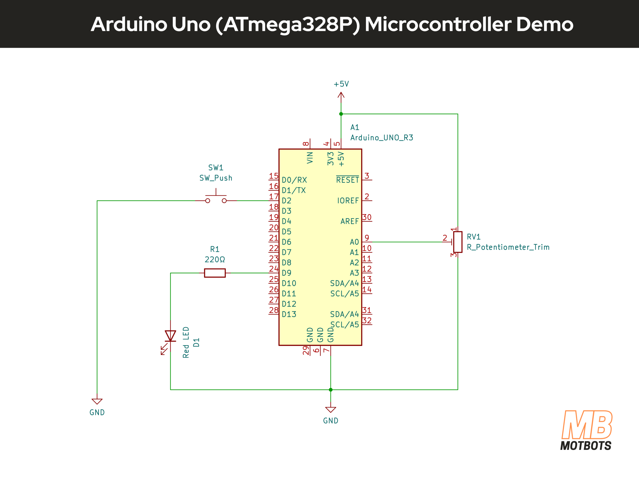
Before we begin this first mini-project, review the following parts list of items and schematic diagram we’ll need to perform this build:
Parts List
| Item | Quantity |
| Arduino Uno | 1 |
| 10k potentiometer | 1 |
| Red LED | 1 |
| 220Ω resistor | 1 |
| Momentary push-button switch | 1 |
| Solderless breadboard | 1 |
| Jumper wires | Various sizes and colors |
Schematic Diagram of Arduino Uno Microcontroller Demo
The following image is a schematic diagram of the mini-project we’re performing showing the Arduino Uno microcontroller in circuit with connected components as should be done when making your prototype circuit.
Arduino Uno Datasheet
I’ve provided the datasheet from ArduinoDocs for the Arduino Uno, below. You may obtain this datasheet directly from the Arduino website here, or you may download the datasheet by clicking on the image below.
Breadboard Assembly
For this demonstration, I will be using a 400-point breadboard for its small size, since this is a mini-project that uses few components. You may use any size you’d like.
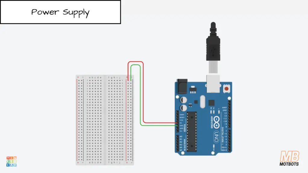
Breadboard Power Supply Setup
Facing the 400-point breadboard vertically, with the letters and numbers of the breadboard’s columns and rows facing right side up, I used the right side power rail of the breadboard as my power supply rails.
I connected a red jumper wire from the upper terminal of the right-side positive power rail on the breadboard to the 5V pin on the Arduino Uno. I then connected a green jumper wire from the upper terminal of the right-side negative power rail to the GND pin located next to the 5V pin on the Arduino.
In this setup, the Arduino is powered via USB from my computer, and I am using the board’s onboard regulated 5V supply to power the breadboard rails.
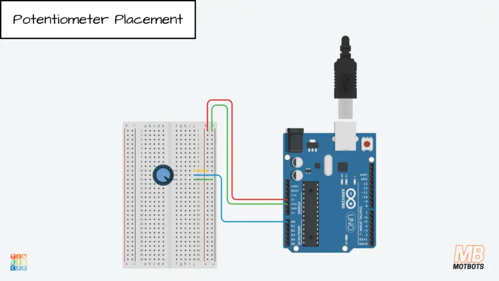
Potentiometer Placement
My potentiometer has a 3-terminal inline setup, I guess we can call it — meaning that its terminals are inline with each other, unlike other trimpots that can have staggered or offset terminals.
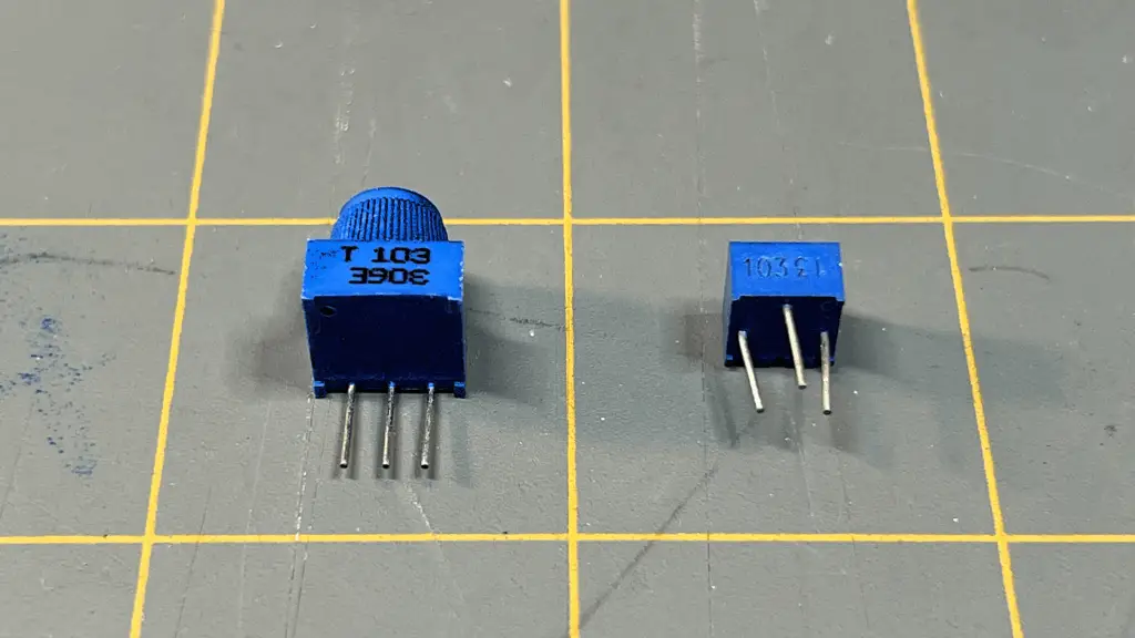
I placed my pot’s terminals at points f10-f12, on the breadboard — the center terminal or wiper of the pot being at point f11.
I connected a long blue jumper wire from pin A0 of the Arduino to point j11 on the breadboard — inline with the center pin or wiper of the potentiometer.
Next, I connected a short yellow jumper wire from point j10 — inline with the outside pin of the potentiometer, to an adjacent point on the positive power supply rail on the breadboard.
To finish up the connections for the potentiometer, I connected a short green jumper wire from the point j12 — inline with the other outside pin of the potentiometer, to a point on the adjacent negative power supply rail on the breadboard.
Push-Button Placement
Moving on to the momentary push-button switch. I’m using a two-terminal push-button switch. I placed its terminals at points h20 and h22.
I connected a long orange jumper wire from pin 2 of the Arduino Uno to point j22 on the breadboard — inline with the pin of the push-button switch.
To complete the connections for the push-button switch, I connected a short green jumper wire to point j20 — inline with the other pin of the push-button switch to a point on the adjacent negative power supply rail on the breadboard.

Resistor and LED Placement
We will complete our circuit by connecting the 220Ω resistor and red LED to the Arduino from the breadboard.
First, I placed the 220Ω resistor at points f1 and f5. Then, I connected a long yellow jumper wire from pin 3 of the Arduino Uno to point j1 of the breadboard — inline with the resistor pin.
Next, I placed the anode (+) of the red LED at point i5 on the breadboard — inline with the other pin of the resistor, then placed the cathode (-) of the LED to a point on the adjacent negative power supply rail on the breadboard.

Now that our breadboard circuit assembly is complete, we’re now ready to create the code and upload it to the Arduino Uno.
We will not go in depth here on coding — except on pin assignment and the code explanation below, and we will not go over uploading the code to the Arduino.
If you need help on uploading and taking care of certain errors you may encounter, please visit our OwlBot project page for Part 1, where we go over Compiling and Uploading the Code to Arduino and Possible Errors and How to Fix Them, there on that page.
How to Assign Arduino Uno Pin Values in Code
When writing Arduino programs, it’s best practice to assign pin numbers to named variables at the top of your sketch. This makes your code easier to read, easier to modify, and less error-prone.
Instead of writing raw numbers throughout your code like this:
pinMode(3, OUTPUT);
digitalWrite(3, HIGH);It’s better to define the pin once:
const uint8_t LED_PIN = 3;

pinMode(LED_PIN, OUTPUT);
digitalWrite(LED_PIN, HIGH);If you later move the LED to another pin, you only change the value in one place.
Basic Pin Assignment Syntax
For the Arduino Uno R3 (using the ATmega328P), pin assignments are typically written like this:
const uint8_t BUTTON_PIN = 2;
const uint8_t LED_PIN    = 3;
const uint8_t POT_PIN = A0;- const ensures the value cannot change.
- uint8_t is an 8-bit unsigned integer (perfect for pin numbers 0–19).
- The name describes the purpose of the pin.
Common Pin Assignment Examples
| Purpose | Example Code | Notes |
| Digital Output | const uint8_t LED_PIN = 3; | D3 supports PWM |
| Digital Input | const uint8_t BUTTON_PIN = 2; | D2 supports external interrupt |
| Analog Input | const uint8_t POT_PIN = A0; | A0 reads 0–1023 |
| PWM Output | const uint8_t PWM_PIN = 10; | Must be PWM-capable pin |
| Onboard LED | const uint8_t LED_PIN = 13; | Built-in LED on Uno |
Arduino Uno Pin Mapping (Physical → Arduino Code)
🔵 Digital Pins (D0–D13)
| Arduino Pin Label | ATmega328P Port.Bit | Special Function | Value Used in Code |
| D0 (RX) | PD0 | RXD (UART Receive) | 0 |
| D1 (TX) | PD1 | TXD (UART Transmit) | 1 |
| D2 | PD2 | INT0 | 2 |
| D3 | PD3 | INT1, PWM | 3 |
| D4 | PD4 | — | 4 |
| D5 | PD5 | PWM | 5 |
| D6 | PD6 | PWM | 6 |
| D7 | PD7 | — | 7 |
| D8 | PB0 | — | 8 |
| D9 | PB1 | PWM (OC1A) | 9 |
| D10 | PB2 | PWM, SPI (SS) | 10 |
| D11 | PB3 | PWM, SPI (MOSI) | 11 |
| D12 | PB4 | SPI (MISO) | 12 |
| D13 | PB5 | SPI (SCK), LED | 13 |
🟢 Analog Pins (A0–A5)
| Arduino Pin Label | ATmega328P Port.Bit | ADC Channel | Value Used in Code |
| A0 | PC0 | ADC0 | A0 or 14 |
| A1 | PC1 | ADC1 | A1 or 15 |
| A2 | PC2 | ADC2 | A2 or 16 |
| A3 | PC3 | ADC3 | A3 or 17 |
| A4 | PC4 | ADC4, SDA | A4 or 18 |
| A5 | PC5 | ADC5, SCL | A5 or 19 |
🤔 What Do You Actually Write in Code?
For digital pins:
pinMode(3, OUTPUT);For analog pins:
analogRead(A0);Technically, A0 equals 14 internally, but you should always use A0 in code for clarity.
🤔 Why Does the Pinout Diagram Show Multiple Numbers?
To answer this question, let’s refer to the pinout diagram below. You may obtain the Arduino Uno pinout diagram below or directly from the Arduino website here.
For example:
D0 (RX) may show:
- Physical pin number on the DIP chip
- PD0 (Port D, bit 0)
- RXD (UART function)
- Arduino number 0
But in Arduino code, you only use 0. Arduino handles the port mapping internally.
Why This Mapping Matters
Understanding this table helps you:
- Write register-level code (DDRB, PORTD, etc.)
- Debug hardware-level behavior
- Understand timer-to-pin relationships (e.g., D9 = OC1A)
For example:
D9 → PB1 → OC1A → Timer1 output compare A
That’s why Timer1 controls PWM on D9.
Although each Arduino pin corresponds to a specific ATmega328P port and bit (such as PD0 or PB1), Arduino code uses the simplified numeric labels (0–13 and A0–A5). The Arduino core handles the hardware mapping internally.
Code for Arduino Uno Microcontroller Demo
/* ------------------------------------------------------------------------------
 * Project: OwlBot: Arduino Uno (ATmega328P) Microcontroller Demonstration
 * Written by: Dustin Hodges (Motbots)
 * Date Created: 02/23/2026
 * Date Last Modified: 02/25/2026
 * Description: This is a supplemental mini-project for the article titled
 * "Microcontroller 101: A Brief on GPIO, Timers, ADC, PWM, and Interrupts (ATmega328P)"
 * found at the Motbots website (link below).
 *
 * - Pot on A0 controls LED brightness on D9 (PWM)
 * - Button on D2 uses external interrupt to toggle enable/disable
 * - Timer1 interrupt runs every 10 ms to schedule work (non-blocking)
 *
 * Wiring:
 *
 * - Pot: outer legs to 5V and GND, wiper to A0
 * - LED: D3 -> resistor (220Ω) -> LED anode, LED cathode -> GND
 * - Button: D2 -> button -> GND (uses INPUT_PULLUP)
 *
 * Microcontroller Board: Arduino Uno R3
 * IDE Version: Arduino IDE 2.3.7
 * Article Location: https://motbots.com/microcontroller-101-atmega328p/
 * Circuit Parts List Location: https://motbots.com/microcontroller-101-atmega328p/#Parts_List
 * Circuit Schematic Location: https://motbots.com/microcontroller-101-atmega328p/#Schematic_Diagram_of_Arduino_Uno_Microcontroller_Demo
 * ------------------------------------------------------------------------------
 */

#include <Arduino.h>

const uint8_t PWM_PIN = 3;      // PWM output pin D3 on Uno
const uint8_t POT_PIN = A0;     // ADC input pin A0 on Uno
const uint8_t BTN_PIN = 2;      // External interrupt pin (INT0), pin D2 on Uno

volatile bool g_enabled = true;
volatile bool g_tickFlag = false;

volatile bool g_buttonEvent = false;
volatile unsigned long g_lastPressUs = 0;

void onButtonInterrupt() {
  unsigned long now = micros();

  // 50 ms debounce window
  if (now - g_lastPressUs >= 50000UL) { // 50 ms debounce window
    g_buttonEvent = true;      // signal a press event
    g_lastPressUs = now;       // start debounce window
  }
}

void setupTimer1_10ms() {
  // Configure Timer1 in CTC mode for 10ms interrupts.
  // Arduino Uno clock: 16 MHz
  // Prescaler 64 => timer tick = 16MHz/64 = 250kHz (4 us per tick)
  // 10 ms / 4 us = 2500 counts
  // OCR1A = 2500 - 1 = 2499

  noInterrupts();

  TCCR1A = 0;
  TCCR1B = 0;
  TCNT1  = 0;

  TCCR1B |= (1 << WGM12);              // CTC mode
  TCCR1B |= (1 << CS11) | (1 << CS10); // prescaler 64
  OCR1A = 2499;

  TIMSK1 |= (1 << OCIE1A);             // enable compare match interrupt

  interrupts();
}

ISR(TIMER1_COMPA_vect) {
 // Don't do heavy work here—just set a flag
 g_tickFlag = true;
}

void setup() {
  pinMode(PWM_PIN, OUTPUT);
  pinMode(BTN_PIN, INPUT_PULLUP); // button to GND

  attachInterrupt(digitalPinToInterrupt(BTN_PIN), onButtonInterrupt, FALLING);

  setupTimer1_10ms();
}

void loop() {
  // Only do the main work when the timer says it's time
  if (g_tickFlag) {
    g_tickFlag = false;

    if (g_buttonEvent) {
      g_buttonEvent = false;
      g_enabled = !g_enabled;
    }

    if (g_enabled) {
      int adc = analogRead(POT_PIN);          // 0..1023
      uint8_t duty = adc >> 2;                // scale to 0..255
      analogWrite(PWM_PIN, duty);             // PWM duty control
    } else {
      analogWrite(PWM_PIN, 0);                // disabled => LED off
    }
  }

  // The loop stays free for future features (serial print, extra sensors, etc.)
}
The Code Explained
Comment Header
/* ------------------------------------------------------------------------------
 * Project: OwlBot: Arduino Uno (ATmega328P) Microcontroller Demonstration
 * Written by: Dustin Hodges (Motbots)
 * Date Created: 02/23/2026
 * Date Last Modified: 02/25/2026
 * Description: This is a supplemental mini-project for the article titled
 * "Microcontroller 101: A Brief on GPIO, Timers, ADC, PWM, and Interrupts (ATmega328P)"
 * found at the Motbots website (link below).
 *
 * - Pot on A0 controls LED brightness on D9 (PWM)
 * - Button on D2 uses external interrupt to toggle enable/disable
 * - Timer1 interrupt runs every 10 ms to schedule work (non-blocking)
 *
 * Wiring:
 *
 * - Pot: outer legs to 5V and GND, wiper to A0
 * - LED: D3 -> resistor (220Ω) -> LED anode, LED cathode -> GND
 * - Button: D2 -> button -> GND (uses INPUT_PULLUP)
 *
 * Microcontroller Board: Arduino Uno R3
 * IDE Version: Arduino IDE 2.3.7
 * Article Location: https://motbots.com/microcontroller-101-atmega328p/
 * Circuit Parts List Location: https://motbots.com/microcontroller-101-atmega328p/#Parts_List
 * Circuit Schematic Location: https://motbots.com/microcontroller-101-atmega328p/#Schematic_Diagram_of_Arduino_Uno_Microcontroller_Demo
 * ------------------------------------------------------------------------------
*/This is just a comment block (human-readable notes). It tells you what the program is intended to do.
Pin definitions (GPIO planning)
const uint8_t PWM_PIN = 3;      // PWM output pin D3 on Uno
const uint8_t POT_PIN = A0;     // ADC input pin A0 on Uno
const uint8_t BTN_PIN = 2; // External interrupt pin (INT0), pin D2 on Uno- const means values won’t change.
- uint8_t is an 8-bit unsigned integer (0–255). Great for pin numbers.
- PWM_PIN = 3 means we will output PWM on digital pin 3 (supports PWM).
- POT_PIN = A0 means we read the potentiometer voltage on analog pin A0 (ADC input).
- BTN_PIN = 2 means button input uses digital pin 2, which supports external interrupt INT0.
⚠️ Design Note: Timer Resource Conflict
Since Timer1 is configured for 10 ms interrupts, we cannot use PWM pins driven by Timer1 (D9, D10). Therefore, PWM output was moved to D3, which is controlled by Timer2.
On the Uno, D3 is driven by Timer2.
Shared variables used by interrupts
volatile bool g_enabled = true;
volatile bool g_tickFlag = false;- bool means true/false.
- volatile is very important: it tells the compiler, “This variable might change unexpectedly (like inside an ISR), so don’t optimize it away.”
What they mean:
- g_enabled = whether the LED PWM control is active.
- g_tickFlag = a flag set by the Timer interrupt to tell the main loop “it’s time to do an update.”
External interrupt ISR (button)
volatile bool g_buttonEvent = false;
volatile unsigned long g_lastPressUs = 0;

void onButtonInterrupt() {
  unsigned long now = micros();

  // 50 ms debounce window
  if (now - g_lastPressUs >= 50000UL) { // 50 ms debounce window
    g_buttonEvent = true;      // signal a press event
    g_lastPressUs = now;       // start debounce window
  }
}This function runs when the button interrupt triggers.
- Checks whether 50 ms have passed since the last valid press
- If so, signals a button event
- Starts a new debounce window
The ISR does not change system state directly. It only signals that a press occurred. This keeps the interrupt short and predictable, which is best practice in embedded systems.
Why keep it short? ISRs should be fast so they don’t block other interrupts.
Timer setup function
void setupTimer1_10ms() {This function configures Timer1 to generate an interrupt every 10 milliseconds.
Timer math comments
  // Configure Timer1 in CTC mode for 10ms interrupts.
  // Arduino Uno clock: 16 MHz
  // Prescaler 64 => timer tick = 16MHz/64 = 250kHz (4 us per tick)
  // 10 ms / 4 us = 2500 counts
// OCR1A = 2500 - 1 = 2499This explains the reasoning for choosing OCR1A = 2499.
- The Arduino Uno clock is 16 MHz.
- With prescaler 64, timer increments at 250 kHz.
- 250 kHz = 1 tick every 4 microseconds.
- We want 10 ms = 10,000 µs.
- 10,000 µs / 4 µs = 2500 ticks.
- Timer compares to OCR1A starting at 0, so 2500 ticks means OCR1A should be 2499.
Disable interrupts while configuring hardware registers
noInterrupts();Temporarily turns off interrupts so the timer doesn’t fire while we’re setting it up.
Clear timer control registers
  TCCR1A = 0;
  TCCR1B = 0;
TCNT1 = 0;These are Timer/Counter Control Registers for Timer1. Setting them to 0 starts from a known clean state.
TCNT1 stands for: Timer/Counter 1 Register
It is the actual 16-bit counter register for Timer1. When Timer1 runs, this register:
- Starts at some value
- Increments every timer tick
- Compares against OCR1A
- Resets in CTC mode
So TCNT1 is literally the running timer value. When TCNT1 = 0, it resets the Timer1 counter back to zero.
Set CTC mode
TCCR1B |= (1 << WGM12); // CTC mode- WGM12 is a bit that selects CTC mode (Clear Timer on Compare).
- In CTC mode, Timer1 counts up until it matches OCR1A, then resets to 0 automatically.
On the ATmega328P (Arduino Uno), TCCR1B is a hardware register. It stands for Timer/Counter Control Register 1B. It’s an 8-bit register that controls:
- Timer1
- Prescaler selection
- Other timer behavior
Each bit inside that register controls something specific.
WGM12 is a bit position constant. It tells the compiler which bit inside TCCR1B corresponds to Waveform Generation Mode bit 12.
For Timer1, CTC mode requires setting WGM12 = 1.
On the ATmega328P, WGM12 is bit 3 of TCCR1B. So, effectively:
WGM12 = 3The (1 << WGM12) is called a bit shift. The << operator means “shift left”. So, (1 << WGM12) means:
- Take binary 00000001
- Move it left by WGM12 positions
If WGM12 = 3, then:
00000001 << 3becomes:
00001000Which is decimal 8.
| Powers of 2 | Binary | Conversion | Decimal |
| 27 26 25 24 23 22 21 20 | 00001000 | 0 + 0 + 0 + 0 + 23 + 0 + 0 + 0 = 8 | 8 |
So, (1 << WGM12) creates a binary mask that targets exactly one bit. The |= is a compound operator. It means:
TCCR1B = TCCR1B | something;The | symbol is a bitwise OR. Bitwise OR works like this:
| A | B | Result |
| 0 | 0 | 0 |
| 0 | 1 | 1 |
| 1 | 0 | 1 |
| 1 | 1 | 1 |
So OR:
- Leaves 1 bits as 1
- Only sets bits to 1
- Never clears bits
So, the entire TCCR1B |= (1 << WGM12); means:
- Create a mask with only bit 3 set
- OR that mask into TCCR1B
- Set that one bit to 1
- Leave all other bits unchanged
It is the safe way to turn on one specific bit in a hardware register.
Set prescaler to 64
TCCR1B |= (1 << CS11) | (1 << CS10); // prescaler 64This line configures the Timer1 prescaler on the ATmega328P (Arduino Uno). This sets Timer1 prescaler bits to choose divide-by-64 clock.
TCCR1B is an 8-bit hardware control register for Timer1. Inside it are several control bits. The ones we care about here are:
| Bit | Name | Purpose |
| 2 | CS12 | Clock Select |
| 1 | CS11 | Clock Select |
| 0 | CS10 | Clock Select |
These three bits together determine the timer prescaler.
The Arduino Uno runs at 16 MHz. That’s very fast. The prescaler divides that clock before feeding it into Timer1.
The combination of CS12, CS11, and CS10 selects the division amount. For Timer1:
| CS12 | CS11 | CS10 | Prescaler |
| 0 | 0 | 0 | Timer stopped |
| 0 | 0 | 1 | ÷1 |
| 0 | 1 | 0 | ÷8 |
| 0 | 1 | 1 | ÷64 |
| 1 | 0 | 0 | ÷256 |
| 1 | 0 | 1 | ÷1024 |
So for divide-by-64:
CS12 = 0
CS11 = 1
CS10 = 1
That’s what this line is setting. This creates a bit mask that turns on the CS11 bit.
CS11 = 1Then:
1 << CS11becomes:
00000010Similarly:
1 << CS10becomes:
00000001The | between them is bitwise OR. So we combine:
00000010
00000001
--------
00000011
That produces:
00000011Which means:
- CS12 unchanged (still 0 if previously 0)
- CS11 = 1
- CS10 = 1
This corresponds to prescaler ÷64.
This part:
TCCR1B |= means:
TCCR1B = TCCR1B | (that bit mask)So, it turns on CS11 and CS10, and leaves all other bits in TCCR1B unchanged. This is critical, because we don’t want to accidentally overwrite WGM12 and other control bits. We only want to modify those two prescaler bits.
Set compare value
OCR1A = 2499;This is the number Timer1 counts up to before triggering the compare interrupt.
Enable the Timer1 compare interrupt
TIMSK1 |= (1 << OCIE1A); // enable compare match interrupt- TIMSK1 = Timer Interrupt Mask register for Timer1
- OCIE1A enables the “Output Compare A Match” interrupt for Timer1
Re-enable interrupts
  interrupts();
}Turns interrupts back on.
Timer ISR (runs every 10 ms)
ISR(TIMER1_COMPA_vect) {
 // Don't do heavy work here—just set a flag
 g_tickFlag = true;
}This is the Interrupt Service Routine for Timer1 compare match A. It fires every 10 ms because of the setup above.
Inside the ISR we do only one thing:
- set g_tickFlag = true;
That tells loop() it’s time to update the ADC and PWM.
setup() (runs once)
void setup() {Arduino runs setup() once at startup.
Set pin modes (GPIO)
pinMode(PWM_PIN, OUTPUT);- Pin 3 becomes an output pin (drives PWM).
pinMode(BTN_PIN, INPUT_PULLUP); // button to GND- Pin 2 becomes an input.
- Internal pull-up resistor is enabled.
- So the button should connect pin 2 to GND when pressed.
Unpressed = HIGH
Pressed =  LOW
You are enabling the Arduino’s internal pull-up resistor. That means internally the pin is connected to +5V through a resistor. So:
🔵 When the button is NOT pressed
- The circuit to ground is open.
- The pull-up resistor gently pulls the pin to +5V.
- The pin reads HIGH.
🔵 When the button IS pressed
- The button connects the pin directly to GND.
- The voltage drops to 0V.
- The pin reads LOW.
You get:
| Button State | Pin Voltage | digitalRead() |
| Unpressed | ~5V | HIGH |
| Pressed | 0V | LOW |
Using INPUT_PULLUP:
- Eliminates the need for an external resistor
- Prevents floating inputs
- Makes wiring simple (button to GND only)
The only thing to remember is the logic becomes inverted.
Pressed = LOW
Unpressed = HIGH
Attach external interrupt for the button
attachInterrupt(digitalPinToInterrupt(BTN_PIN), onButtonInterrupt, FALLING);This means:
- Use the interrupt hardware for pin 2
- When the signal goes from HIGH to LOW (falling edge),
- Call the function onButtonInterrupt()
This happens immediately when pressed — not only when loop checks.
Configure Timer1
  setupTimer1_10ms();
}Calls the timer setup function.
loop() (runs forever)
void loop() {Only do work when the timer flag is set
if (g_tickFlag) {This checks whether the timer interrupt has occurred since last update. If false, loop does almost nothing (non-blocking).
Clear the flag
g_tickFlag = false;We clear it so we only run once per timer tick.
Handle Button Event
if (g_buttonEvent) {
  g_buttonEvent = false;
  g_enabled = !g_enabled;
}The main loop checks whether the interrupt signaled a button event. If so:
- The system toggles enable/disable state.
- The event flag is cleared.
By separating detection (interrupt) from action (main loop), the system becomes more stable and easier to expand.
If enabled, read ADC and write PWM
if (g_enabled) {Read the potentiometer (ADC)
int adc = analogRead(POT_PIN); // 0..1023Reads analog pin A0:
- returns 0–1023 (10-bit ADC)
Scale 10-bit ADC to 8-bit PWM
uint8_t duty = adc >> 2; // scale to 0..255- adc is 0–1023
- PWM expects 0–255
- Shifting right by 2 divides by 4:
\begin{equation}
\frac{1023}{4}\approx255
\end{equation}
Output PWM
analogWrite(PWM_PIN, duty); // PWM duty controlSets pin 3 PWM duty cycle. A higher duty = a brighter LED.
If disabled, force LED off
} else {
  analogWrite(PWM_PIN, 0);                // disabled => LED off
}When g_enabled is false, PWM duty is set to 0 (LED off).
End of if block and loop
 }

 // The loop stays free for future features (serial print, extra sensors, etc.)
}Big-picture summary
The Arduino program creates a simple embedded “system loop”:
- GPIO: sets up output (LED) and input (button) pins.
- ADC: reads potentiometer value.
- PWM: sets LED brightness based on ADC.
- External interrupt: button signals a press event.
- Main loop: processes the event and toggles enable/disable.
- Timer interrupt: provides a steady 10 ms “heartbeat” so the system updates regularly without using delay().
The system now uses two hardware timers independently: Timer1 for scheduling and Timer2 for PWM output.
Potentiometer Demo: Arduino Uno (ATmega328P) Microcontroller


Push-Button Demo: Arduino Uno (ATmega328P) Microcontroller


Final Thoughts
The ATmega328P shows us something powerful: complex behavior can emerge from a handful of well-understood hardware modules. GPIO lets us connect to the outside world. Timers let us measure and control time. ADC lets us sense analog reality. PWM lets us control power smoothly. Interrupts let our systems respond instantly instead of constantly checking and waiting.
On the Arduino Uno, many of these features are wrapped in friendly functions like pinMode(), analogRead(), and analogWrite(). That abstraction lowers the barrier to entry — and that’s a good thing. But behind those simple function calls are real hardware registers and real timing math. As you grow more comfortable, you’ll begin to see past the abstraction layer and understand how the microcontroller truly operates.
Mastering these fundamentals is what moves you from “uploading sketches” to designing embedded systems. And once you understand these building blocks, you’ll find that nearly every intelligent device you encounter — from appliances to robots — is built on these same principles.
This is where embedded intelligence begins.

What’s Next
Now that you’ve seen how the ATmega328P handles GPIO, timers, ADC, PWM, and interrupts through the Arduino ecosystem, it’s time to peel back another layer.
In the next article, we’ll explore these same fundamental building blocks — but this time on the PIC18F4525. Unlike the Arduino environment, the PIC approach requires direct register configuration and a deeper awareness of how each hardware module operates. You won’t just call a function — you’ll configure the bits yourself.
This isn’t about replacing Arduino. It’s about expanding your understanding.
By comparing the ATmega328P and the PIC18F4525 side by side, you’ll begin to see something important: while the syntax and setup may differ, the core principles remain the same. GPIO still connects you to the outside world. Timers still divide clock cycles into usable time. ADC still translates voltage into data. PWM still controls power. Interrupts still make systems responsive.
The platform may change, but the fundamentals do not — and that realization is a major step forward in mastering embedded systems.
Remember to keep at it and stay motivated.