How to Make an OwlBot: The Bird Intimidator – Part 6 (Section 1): PCB Circuit Build
| Project Name: | OwlBot |
| Project Description: | In this section of Part 6, we begin the process of transferring our components from the breadboard to the PCB. We also get into making our own wire connectors for this project. |
| Project Difficulty: | Moderate |
| Project Note: | For this part of the project we will be using a soldering iron and heat-gun. Use caution when handling hot items. |
Introduction
In this part of the project we’re going to be performing the first section of the sixth step of what will eventually be the OwlBot. The OwlBot will be a device that can be used as a bird intimidation tool to scare away pesky birds in the yard, around the house or barn, at restaurants, or in trees, bushes, and gardens. Hence, the phrase, “The Bird Intimidator”.

The OwlBot (a.k.a. “The Bird Intimidator”) we’ll be making will be done in several parts. The OwlBot is an ambitious project. When complete, the OwlBot will sense motion. When motion is detected, the OwlBot should make owl sounds, perform varying movements, and flash its red eyes to intimidate and scare away pests. To put together all these tasks in one page would be too long and cumbersome, so we’ve decided to split each process we want the OwlBot to do into easy to accomplish chunks or parts as we continue on our goal to complete the OwlBot.

This is Part 6 (Section I)
This is the first section of part six. The sixth part of the OwlBot project will involve us transferring our prototype circuit from the breadboard to a more permanent prototype PCB board to be placed inside our owl figure, later in the build process. The following are what we’ve done for each part of the entire project series, up to this point:
- We added a PIR sensor to the Arduino Uno we’re using as the brains for the OwlBot. The PIR sensor will capture any movement from critters that crosses the OwlBot’s path, which will in turn produce the signal we need to tell the Arduino to perform other functions, like flash some red LEDs and play sounds on an MP3 player. We added the PIR sensor in Part 1 of the project series.
- We connected a DFPlayer Pro Mini MP3 Player to our circuitry to allow the OwlBot to produce owl sounds from the MP3 player to a pair of speakers when motion is detected by the PIR sensor. We added the MP3 player and speakers in Part 2 of the project series.
- We gave the OwlBot the ability to have flashing red eyes when motion is detected by the PIR sensor by adding a couple red LEDs to our circuitry. We added the LEDs in Part 3 of the project series.
- We upgraded the power supply for the OwlBot (actually, we added a secondary power supply) to help power a DC motor and a couple of solenoids we’d add later in the project series. We added the secondary 9V battery supply made of 6AA batteries and formed a common ground for our circuitry in Part 4 of the project series.
- As for the most recent part of the project series, we added mechanical movement to the OwlBot with the help of a DC motor and two solenoids. Both of these devices will add movement to the OwlBot – a much needed characteristic for this project to be able to scare away pesky critters. We added the DC motor and solenoids in Part 5 of the project series.
- For Part 6, we’re going to take what we’ve done on the breadboard and transfer it all to a more permanent solution. We’re going to need to solder our components to our PCBs.
First, we’ll create a hand-drawn circuit on paper, that will replicate the generic PCB boards that we’ll use for our circuitry. We’ll use this hand-drawn circuit to help us determine where each component we’ve added during our prototyping phases of the project should go. A hand-drawn circuit will make it easier for us to make changes or correct errors as we progress through the following processes to make a completed working permanent circuit.
Once we’re happy with our hand-drawn circuit, we’ll use it as our guide to transfer each component to its respective place on the PCB, to then be soldered permanently.

Goal of Part 6 of the OwlBot Project
Our goal at the end of this part of the project will be to have a working permanent circuit for our OwlBot. It’s not ideal having our somewhat complex circuit being left on a breadboard. Having a permanent circuit will ensure that our OwlBot will last, will perform how we want it to, reduce the chances of having our circuit fail, and help us to achieve the end goal of having our project be more robust and portable. After all, we do want to actually use our OwlBot when everything is said and done.
For this part of the build, we should perform and complete the following tasks:
- Create a hand-drawn schematic diagram that shows an accurate description of how our permanent circuit should look in real life.
- Methodically transfer each component from the breadboard prototype circuit to the PCB perfboard and solder them in place, as we had described in our hand-drawn schematic diagram.
- Test the permanent PCB circuit once we feel that our circuit is ready, and identify and correct any issues that might arise during the testing phase.
Hand-Drawing the PCB Schematic Diagram
I know what you’re thinking, “Why are we going to draw our schematic diagram by hand? Can’t we just use some type of software that’ll allow us to quickly draw up whatever we need?” The answer to this is yes, probably, but there are a couple of reasons why I like to draw my PCB schematic diagrams by hand at this point of any build that I do, and I’d like to try to sell my reasoning to you.
The reasons as to why I like to draw my PCB schematic diagram are as follows:
- Helps to Create a Visual Aid: When drawing a schematic diagram by hand, I can draw it to the best of my ability as the circuit should look in the real world. This helps me to visualize how components should connect on the PCB and to determine exactly where they can go. This is especially helpful when using a generic prototype PCB board – I can draw the exact PCB with the exact number of through holes – this allows me to determine how I can fit each component and device onto the PCB, down to the exact through hole location where a component lead will go.
- Makes Customization Easy: With a hand-drawn schematic diagram, I can layout how I want the components to be down to the exact through holes on the prototype PCB that we’re using for this project. This allows for total customization for the specific board that is being used. For this project, I am using two different sizes of prototype PCB boards.
- Removes Any Doubt During the Soldering Phase: As I am drawing where I want components to be on the PCB perfboard, I am constantly referencing the circuit schematics that were made in a software program for the early stages of the OwlBot build series – making sure that all connections are correct and as they should be. Once I have my drawing all laid out and I’m ready to begin soldering components to the PCB perfboard, I can do so with more confidence knowing that I have my hand-drawn schematic diagram I drew up beforehand. This helps remove any doubts that could have occurred if I had not taken the extra step of creating a visual aid.
This is not a professionally done project, by any means. If it were, of course we’d want professionally done diagrams and schematics. We’re just having fun here, but we also don’t want to have a bad day by messing up our project by making the wrong solder connections either. Drawing out any visual guides for yourself during a project build can help out tremendously, especially one such as this OwlBot project, since it has several components to deal with.
How to Draw Your PCB Schematic Diagram
If you’re not up to drawing your own schematic diagram, you’re more than welcome to use the one provided below. Just know that it’s customized to the type of boards that I’m using. If you’re using a different version of Arduino microcontroller (Leonardo, Due, Mega, etc.), your PCB prototype shield will obviously be different than mine. If you’re using a different sized PCB prototype board, my drawing won’t be like how the placement of components will be for your type of board.
If you decide to draw your own schematic diagram, don’t fret on perfection. The sole purpose of the drawing is to act as a guide to solder your components in the proper way they need to be, so that you’re not second guessing yourself during the transfer of components from the breadboard to prototype PCB board.
I like to draw components and devices used in my project as they are. I may use schematic symbols, if I think it’ll work for my understanding of a circuit, but having a real representation of something makes assembly and soldering much more easy and comfortable for me. Do what works for you.
Take your time, and know that the most important thing is to make sure that you have all your connections correct. Use the help of the other schematics we used throughout this entire project series. Worry about making your drawing practical, not pretty.
“Worry about making your drawing practical, not pretty.“
Below, is the hand-drawn schematic diagram I drew, if you need it for reference. Click the image to download it and save it.

Using Two Prototype PCB Perfboards
The image above shows the hand-drawn schematic diagram that I made. You can see that there will be two generic prototype PCB boards that I’m using for this project:

I divided the placement of components onto the two separate prototype perfboards:
- Arduino Shield Board: We will fit this shield on top of the Arduino Uno we are using for this project. It will give us a direct connection to all the pins of the Arduino. We will place the MP3 player we added in Part 2 of the series directly to this shield. We will add connectors to this shield for access to the 5V supply from the Arduino. We will add connectors to make a common ground, and we will make our connections for the speakers, PIR sensor, and LEDs for the OwlBot to this shield board, as well.
- 240 hole PCB Prototype Perfboard: We will make our connections for the DC motor and solenoids we are using for this project to this board. We will also make direct connections to the secondary 9V power supply we added in Part 4 of the series, consisting of 6 AA batteries. We will also make a connection from this board to the common ground that we’ll place on the Arduino shield board.
Using two prototype boards was necessary, because there was no way for me to fit all components and connectors used for this project onto the Arduino shield board alone. It also helps to divide common power use devices, such as the lower power devices (PIR sensor, LEDs, and MP3 player) onto one board, and the high power devices (DC motor and solenoids) on the other board. Using two separate prototype boards also follows how we divided our components as we built our prototype circuit throughout this project series.
Let’s Be Methodical
I like to be very methodical about things, so we’ll go step-by-step — in detail — on the entire build of this project: the parts we’ll need, why we’re using them, how to connect them, how they work, and more! First, we’ll start with the following parts list for the items we’ll need for this part of the project:
Parts List
(This parts list is a continuation of the previous parts lists of the OwlBot project, and may contain parts already listed from before.)
| Item | Quantity | Description |
| Arduino Uno Prototype Shield Board | 1 | Refer to Using Two Prototype PCB Perfboards above. |
| 3×7cm double-sided PCB prototype board with 240 holes | 1 | Refer to Using Two Prototype PCB Perfboards above. |
| 22 AWG Solid Core Wire | Various Lengths of Wire (Red, Black, Blue, Orange) | Used to make jumper connections on prototype PCB perfboard. |
| 24 AWG Stranded Wire | Various Lengths of Wire (Red, Black) | Used to make connections for the connectors we’ll make. |
| 680Ω Resistor | 2 | Two of this value of resistor are needed as current limiting resistors for the red LEDs we’re using as the OwlBot’s eyes. |
| 1kΩ Resistor | 1 | This resistor value is used to reduce “noise” and improve sound quality to the speakers. |
| Dupont Connector Kit | 1 kit | We’ll use these to make connections from modules and components to the PCB perfboard. |
| Crimping Tool Kit w/ JST-XH and SYP connector sockets and terminals | 1 kit | We’ll need these to make connections on the PCB board and to homemade wire connectors. |
| Heat Shrink Tubing | Various lengths, sizes, and colors | We’ll use these to protect some of the soldered connections we’ll make. |
Tools Used in Project
| Item | Description |
| Soldering Iron | We need the soldering iron to solder components for our project later. |
| Solder | I used the MG Chemicals rosin core leaded solder with a diameter of 0.025” — Sn63/Pb37 |
| Soldering Iron Tip Cleaner | I use an Aoyue soldering iron tip cleaner with brass wire sponge, but in the past I just used a regular damp dish sponge to clean my solder tips. |
| Wire Stripping Tool | This tool helps in the process of stripping the sheathing off wire. |
| Mini Side Cutters | We’ll be using the cutters to cut things like excess header pins and wire. |
| Dupont Crimping Tool | We’ll use this tool to crimp the Dupont connectors. |
| Heat Shrink Gun | We’ll use this device for heat shrink tubing. |

Soldering Components to the Arduino Prototype Shield Board
The first thing we’ll do is to add the components we need to go onto the Arduino Uno prototype shield board and solder them in place. We’ll reference the hand-drawn schematic diagram we created earlier, so that we can methodically transfer each individual component, one at a time, from the breadboard prototype circuit we made on TUDIY, from parts 1 through 5 of this project series, to the shield board to be soldered.
NOTE: Placement of components and jumper wires in the following steps and images may differ slightly compared to the hand-drawn schematic provided above.

Step 1: Making Positive and Negative Supply Connections

We’ll start off with making the connections from the ground (GND) and 5V through holes of the Arduino Uno prototype shield board. These connections will provide our common ground and +5V supply from the Arduino’s onboard voltage regulator that will power components like the PIR sensor, red LEDs, and MP3 player.
- First, take a couple of small lengths of black 22 AWG solid core wire, strip their ends about ¼-inch and bend both ends of the wires to fit from the through holes at column 18 (next to both GND through holes on the side of the board where +5V is), to the through hole at column 15 (inline with the GND next to the +5V) and to the through hole at column 16 (inline with the other GND), as seen at the circled portion of the schematic diagram image above. Then, solder them in place. The through holes next to GND (on column 18) should be connected via a copper pad that will directly connect them to the GND pins of the Arduino, later when we solder the header pins to our Arduino prototype shield board.
- Next, take a small length of red 22 AWG solid core wire, strip its ends about ¼-inch and bend both ends of the wire to fit from the through hole at column 18 (next to +5V) to the through hole at column 16 (inline with +5V), as seen at the circled portion of the schematic diagram image above. Then, solder it in place. The through hole next to +5V (on column 18) should be connected via a copper pad that will directly connect it to the +5V pin of the Arduino, later when we solder the header pins to our Arduino prototype shield board.

Step 2: Adding the MP3 Player Module

Now that we’ve got the first couple connections made to the prototype PCB shield board, let’s move on to the MP3 player. Looking at the hand-drawn schematic diagram above, we can see that the chosen pin location on the shield board is located along columns 5 and 13.
- The DFPlayer Pro Mini MP3 Player (DFR0768) has a total of 12 pins (6 pins on each side). Place the R-, R+, L-, and L+ pins of the MP3 player inline with the through holes for pins 13, GND, AREF, and SDA, respectively — on the Arduino Uno R3 prototype shield board, along column 5 of the board, as seen in the image below.
- The pins for VIN, GND, RX, TX, DACR, and DACL of the DFPlayer Pro Mini MP3 Player are placed along column 13. Solder all pins in place.

Step 3: Continuing Positive and Negative Supply Connections

We should now have the MP3 player soldered to the Arduino prototype shield board. Now we need to extend the connections we made for the positive and negative supply jumper wires we did in Step 1.
- First, take a length of red 22 AWG solid core wire, strip its ends about ¼-inch and bend both ends of the wire to fit from the through hole (on column 16, inline with row for +3V3) next to the small length of red wire we added earlier for the +5V supply. Solder this wire so that it’s connected to that red wire we added earlier for the +5V supply.
- Next, solder the other end of this new red jumper wire in the through hole inline with the VIN pin of the MP3 player on column 16.
- Now, take a length of black 22 AWG solid core wire, strip its ends about ¼-inch and bend both ends of the wire to fit from the through hole (on column 15, inline with row for +5V) next to the small length of black wire we added earlier for the GND. Solder this wire so that it’s connected to that black wire we added earlier for the GND.
- Next, solder the other end of this new black jumper wire in the through hole inline with the GND pin of the MP3 player on column 15.

Step 4: Adding the Resistors for the LEDs and RX Pin

Next, we need to add the two 680Ω resistors that are the current limiting resistors for the two red LEDs we’re using as the OwlBot’s blinking red eyes we added in Part 3 of this project series. We will also add the 1kΩ resistor for the RX pin of the MP3 player module that we added in Part 2 of this project series.
- Take one 680Ω resistor and place one of its leads into the through hole on the prototype shield board inline with where pin 4 will be on the Arduino, on column 3 of the shield board. This through hole should be connected via a copper pad that will directly connect it to pin 4 of the Arduino, later when we solder the header pins to our Arduino prototype shield board. Place the other terminal of the resistor into a through hole, also inline with where pin 4 will be on the Arduino, on column 7 of the shield board, as seen in the image below.
- Now, take the other 680Ω resistor and place one of its leads into the through hole on the prototype shield board inline with where pin 5 will be on the Arduino, on column 3 of the shield board. This hole should be connected via a copper pad that will directly connect it to pin 5 of the Arduino, later when we solder the header pins to our Arduino prototype shield board. Place the other terminal of the resistor into a through hole, also inline with where pin 5 will be on the Arduino, on column 7 of the shield board, as seen in the image below.
- Solder each of the terminals of both resistors under the bottom-side of the prototype shield board and trim the excess leads off with your cutters.
- Next, let’s take the 1kΩ resistor and place one of its leads into the through hole on the prototype shield board inline with where pin 2 will be on the Arduino, on column 3 of the shield board. This through hole should be connected via a copper pad that will directly connect it to pin 2 of the Arduino, later when we solder the header pins to our Arduino prototype shield board. Place the other terminal of the resistor into a through hole, also inline with where pin 2 will be on the Arduino, on column 7 of the shield board, as seen in the image below.
- Solder each of the terminals of the resistor under the bottom-side of the prototype shield board and trim the excess leads off with your cutters.

Step 5: Making Connections to the RX and TX Pins of the MP3

Once we have the resistors in place from Step 4 (above), we are now ready to make the connections we need to the RX and TX pins of the MP3 player using some more jumper wires.
- First, take a length of blue 22 AWG solid core wire, strip its ends about ¼-inch and bend both ends of the wire to fit from the through hole on column 8, next to the lead of the 1kΩ resistor we soldered on column 7, as seen in the image below. Solder this end of the wire so that it’s connected to that 1kΩ resistor.
- Now, take the other end of the blue jumper wire and place it in the through hole on the prototype shield board on column 13, inline with the 1kΩ resistor. Solder this end of the wire in that through hole.
- Next, take another length of blue 22 AWG solid core wire, strip its ends about ¼-inch and bend both ends of the wire to fit from the through hole on column 13, next to the lead of the blue wire we just added. Solder these leads together, so that we may continue this wire path.
- Now, take the other end of the blue jumper wire and place it in the through hole on the prototype shield board on column 14, next to the RX pin of the MP3 player module. Solder this end of the wire so that it’s connected to that RX pin.
- Next, take a length of orange 22 AWG solid core wire, strip its ends about ¼-inch and bend both ends of the wire to fit from the through hole on column 3, next to where pin 3 will be from the Arduino, as seen in the image below. Solder this end of the wire in place. This through hole we’re soldering this end of the orange wire to should be soldered to the copper pad that will directly connect it to pin 3 of the Arduino, later when we solder the header pins to our Arduino prototype shield board.
- Now, take the other end of the orange jumper wire and place it in the through hole on the prototype shield board on column 14, next to the TX pin of the MP3 player module. Solder this end of the wire so that it’s connected to that TX pin.

Step 6: Adding Connectors and Header Pins

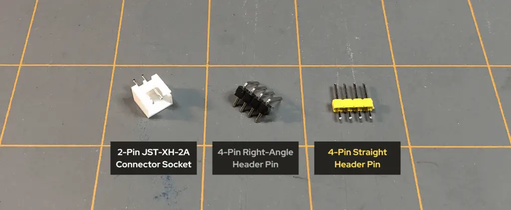
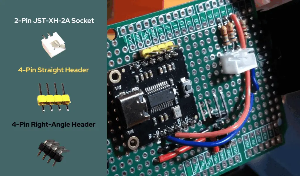
In order to have devices and other items easily be connected and disconnected from our Arduino prototype shield board, we are going to add a few connectors and header pins to it. We are going to add the following connectors:
- A 2-pin JST-XH-2A connector socket to make a connection to the Arduino prototype shield board at the two 680Ω resistors where the LED wiring assembly will connect to that we’ll make later in the build.
- A 4-pin straight header pin for connections to the R-, R+, L-, and L+ pins of the DFPlayer Pro Mini MP3 Player module.
- A 4-pin right-angle header pin for common ground connections to the Arduino prototype shield board.
Let’s start with the 4-pin right-angle header pin for common ground connections to the Arduino prototype shield board. In the video (below), I first connected a 2-pin right-angle header pin, but later decided to add more, so I added a second 2-pin right-angle header pin to make it four pins. So, we’re just going to add a 4-pin right-angle header pin.
- Take a 4-pin right-angle header pin and place it at column 14, having the pins be inline with both GND rows and the rows for +5V and +3V3, on the Arduino prototype shield board. Make sure that the angled pins are pointing toward the center of the shield board and not towards to power connections we made earlier.
- Now, solder the 4-pin right-angle header pin in place. To make it easier to solder and to hold the header pin in place, you can add a piece of tape over the pins to the board to keep the header pins from falling out as you solder them to the underside of the prototype shield board.
- Next, we need to make the connections from each pin of the 4-pin right-angle header to the ground connections we made in steps 1 and 3. Solder each pin of the 4-pin right-angle header together, then solder that whole connection to the black ground wire connections we made in steps 1 and 3, on columns 15 and 16. NOTE: we are only making our connections to ground. DO NOT solder this header to the +5V connections.
- Next, we need to add the 2-pin JST-XH-2A connector socket to the Arduino prototype shield board at column 8, next to and inline with the two 680Ω resistors we added to the shield board in Step 4. Now, solder the 2-pin JST-XH-2A connector socket to the shield board. DO NOT solder the pins of this connector socket together.
- Once you’ve soldered each pin of the 2-pin JST-XH-2A connector socket to the shield board, you need to solder each pin to the corresponding 680Ω resistor lead next to it. This will connect each resistor to its corresponding pin at this connector socket. This connector socket will allow us to connect the two red LEDs we added to the OwlBot prototype circuit in Part 3 of the project series, using a JST-XH-2Y connector socket we’ll setup later in this build.
- Now, let’s take a 4-pin straight header pin and place it at column 4, having the pins be inline with the R-, R+, L-, and L+ pins of the DFPlayer Pro Mini MP3 Player module. NOTE: Make sure that the pins of the header pin are placed on column 4, and not on column 3 – we don’t want this header pin to be in the through holes that would connect it to pins 13, GND, AREF, and SDA of the Arduino. Now, solder the 4-pin straight header pin to the shield board. DO NOT solder the pins of this header pin together.
- Once you’ve soldered each pin of the 4-pin straight header pin to the shield board, you need to connect each pin to the corresponding pin next to it from the MP3 player module – those are the R-, R+, L-, and L+ pins of the DFPlayer Pro Mini MP3 Player module.
Step 7: Assembling a 4-Wire Connector for the Speakers
In Step 6, we added a 4-pin straight header pin to our Arduino prototype shield board next to the R-, R+, L-, and L+ pins of the DFPlayer Pro Mini MP3 Player module. Those pins are for the two speakers we’re using to be able to hear the audio playing from the MP3 player. One “right” speaker (R-, R+), and one “left” speaker (L-, L+). Now, we’re going to create a 4-wire connector we’ll use to connect from the four header pins we just added to the shield board, to each wire of the speakers.
- First, cut a 6 to 8 inch length of red 24 AWG stranded wire and strip its ends about 1/8-inch.
- Next, take a Dupont female connector pin and your Dupont crimping tool, and crimp the female connector pin onto one of the ends of the red wire you just stripped.
- Cut another 6 to 8 inch length of red 24 AWG stranded wire (keep it the same length as the previous wire) and strip its ends about 1/8-inch.
- Take a Dupont female connector pin and your Dupont crimping tool, and crimp the female connector pin onto the end of the second red wire you just stripped.
- Now, cut a 6 to 8 inch length of black 24 AWG stranded wire (keeping it the same length as the two previous red wires) and strip its ends about 1/8-inch.
- Next, take a Dupont female connector pin and your Dupont crimping tool, and crimp the female connector pin onto one of the ends of the black wire you just stripped.
- Cut another 6 to 8 inch length of black 24 AWG stranded wire (keep it the same length as the previous wires) and strip its ends about 1/8-inch.
- Take a Dupont female connector pin and your Dupont crimping tool, and crimp the female connector pin onto the end of the second black wire you just stripped.
Now that we have our four equal lengths of wire prepped (2 red, and 2 black), we can now take a 4-terminal Dupont housing connector and place the four wires we just prepped into the housing of this connector — Dupont female connector pin-side in, as seen in image below.
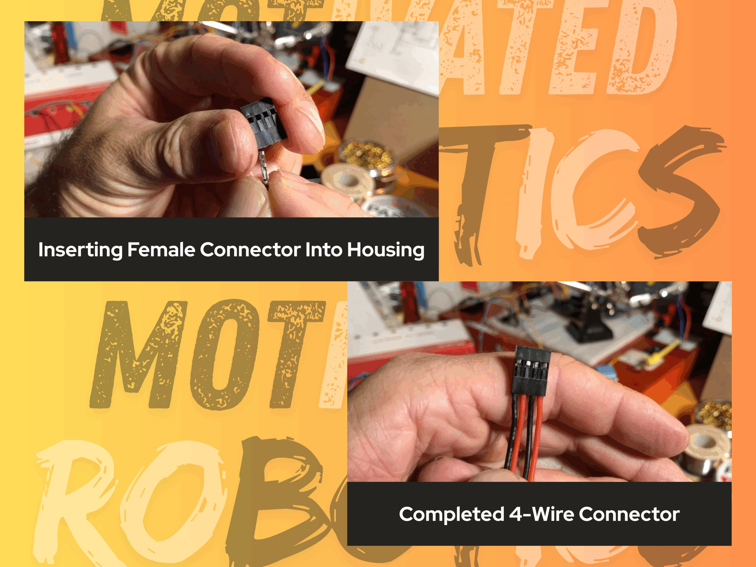
To finish up this 4-wire connector, we need to add Dupont female connectors and the housing to the other ends of the wires, just as we did in the previous steps. Before doing so, I added some electrical tape around the four wires to keep them straight, flat, and neat as I worked, as shown in the image below.
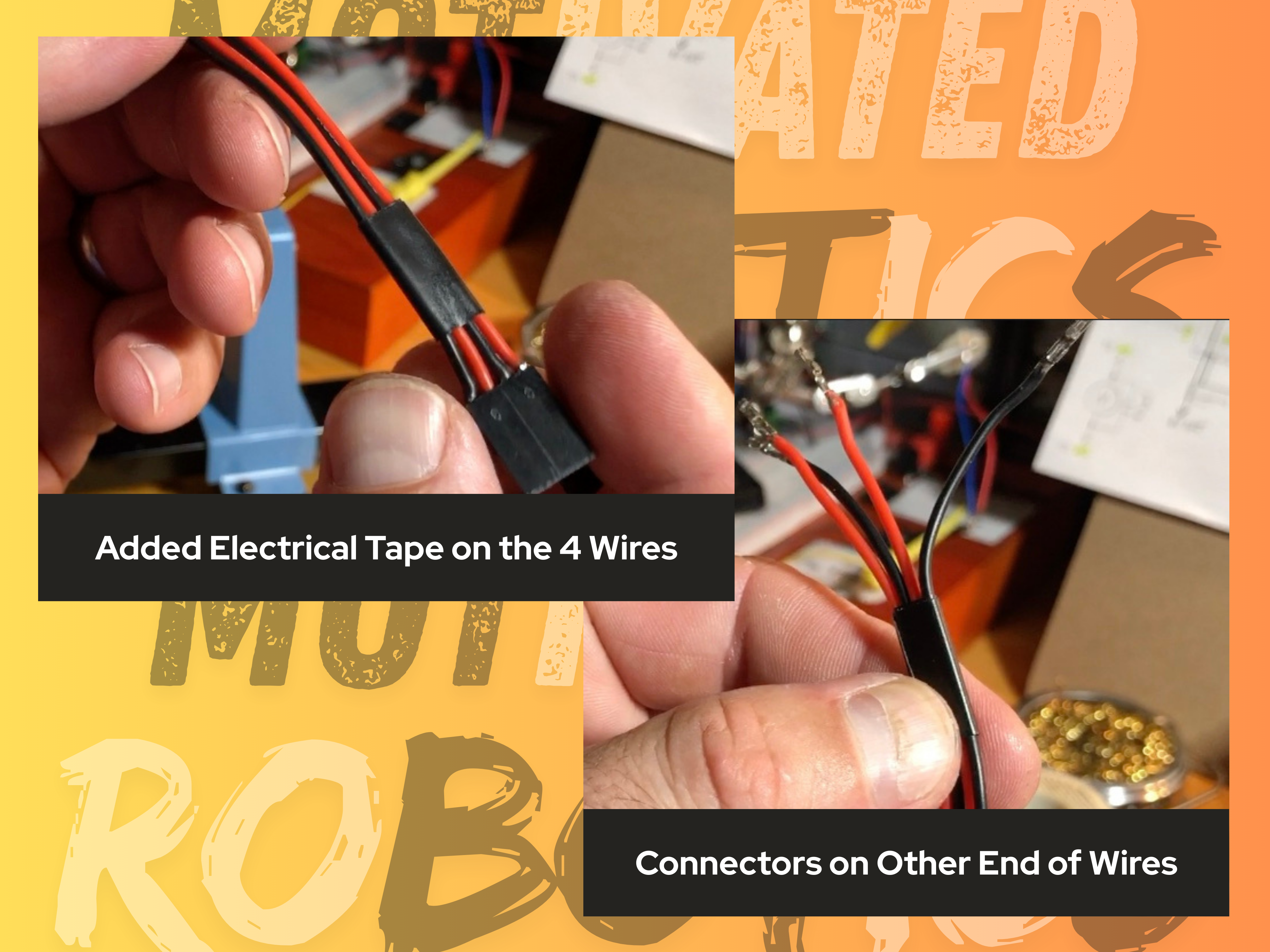
Once the 4-wire connector was assembled and finished, I added more electrical tape to keep the wires flattened out, and to tidy this assembly up a bit, as shown in the image below.

Step 8: Assembling the Wire Connectors for the LEDs
2-Wire Connector
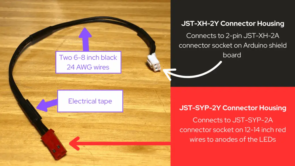
In the video below, Step 8 begins with us creating the connectors for the anodes of the LEDs (of which we’ll get to next, here in Step 8). I had somehow forgotten to record making the 2-wire connector we need for connecting to the PCB shield board at the JST-XH-2A connector socket we soldered to the board in Step 6, which is also to connect to the anodes of the LEDs. The following is how to create the simple 2-wire connector we need first, which should have been part of Step 8, but again, this part was not recorded on video.
- First, cut a 6 to 8 inch length of black 24 AWG stranded wire and strip its ends about 1/8-inch.
- Next, take an SYP female connector pin and your crimping tool (I use a D2032 DxCrimp brand ratcheting crimping tool), and crimp the female connector pin onto the end of the black wire you just stripped.
- Cut another 6 to 8 inch length of black 24 AWG stranded wire (keep it the same length as the previous wire) and strip its ends about 1/8-inch.
- Take an SYP female connector pin and your crimping tool, and crimp the female connector pin onto the end of the second black wire you just stripped.
- Next, take a SYP-2Y connector housing so that we can take the ends of the two black wires we just prepped with SYP female connector pins, and place the pins into the connector housing all the way until they are securely in.
- Now, we want to prepare the other ends of the two black wires to be placed into an XH-2Y connector housing, so that we may be able to plug this end of this 2-wire connector we’re making into the XH-2A connector we soldered to the board in Step 6.
- Take an XH female connector pin and your crimping tool, and crimp the female connector pin onto the other end of one of the black wires.
- Next, take another XH female connector pin and your crimping tool, and crimp the female connector pin onto the other end of the other black wire.
- Now, take an XH-2Y connector housing so that we can take the ends of the two black wires we just prepped with XH female connector pins, and place the pins into the connector housing all the way until they are securely in.
Once this 2-wire connector was assembled and finished, I added electrical tape to tidy-up this assembly.
Connections to the Anodes of the LEDs
In Part 3 of the OwlBot project series, we added a couple of red LEDs to our breadboard prototype circuit to use as the OwlBot’s flashing red LED eyes. Now we want to be able to add those LEDs to our permanent circuitry, but we don’t want to solder them directly to the PCB board. We need to have the LEDs on the head of our owl figure, whereas the PCB circuitry is planned to be at the base of the owl figure. So, we need to be able to wire up and connect the LEDs using long lengths of wire and SYP connectors.
- Cut a 12 to 14 inch length of red 24 AWG stranded wire and strip its ends about 1/8-inch. We’ll need two lengths of wire total, so go ahead and cut yourself another and strip its ends, as well. We need them long in order to reach all the way through the inside of the owl figure from the PCB board (which is planned to be placed at the base of the owl figure), to the LEDs (which will be at the head of the owl figure). In the video below, I had first cut one black and one red length of wire for this part, but later decided on using two 12 to 14 inch lengths of red wire instead.
- Next, take an SYP male connector pin and your crimping tool, and crimp the male pin onto one of the ends of one of the long red wires you just cut and stripped.
- Now, take your other long red wire and another SYP male connector pin and crimp the male pin onto the end of the second long red wire.
- The next thing to do is to get a SYP-2A connector housing that can fit two pins so that we can take the ends of the two red wires we just prepped with SYP male connector pins, and place the pins into the connector housing all the way until they are securely in.
Now that we have one end of both red wires connected to an SYP-2A connector housing, we can now move onto soldering the other ends of the red wires to the anodes of the LEDs.
- We are still working with our two long red wires here. Tin the stripped ends of the red wires that have not been connected to anything yet.
- Next, tin the anodes of the two LEDs we are using from Part 3 of the OwlBot project series.
- Place a piece of heat-shrink tubing over your red wires and slide them out of the way. We’ll use them to protect the solder connections we’ll do next.
- Take one red wire end and solder it to the anode of one of the LEDs.
- Take the other red wire and solder its tinned end to the anode of the second LED.
- Make sure to slide the heat-shrink tubing over your soldered connections of the anodes of the LEDs, and add heat to the tubing – either by using a heat-gun or a lighter (be careful not to burn yourself or anything else) – until they are secure over the soldered connections.
In electronics, tinning is a process of applying melted solder onto an exposed piece of wire or metal surface to make soldering to it easier.

Connections to the Cathodes of the LEDs
Now that we have the anodes of the LEDs connected to our long red wires with the SYP-2A connector at their ends, we now need to make connections to the cathodes of the LEDs, so that we may use a Dupont connector to connect them to the common ground header pins we soldered to our Arduino prototype shield board in Step 6.
- Cut an 18 to 20 inch length of black 24 AWG stranded wire and strip its ends about 1/8-inch. We’ll need two lengths of wire total, so go ahead and cut yourself another and strip its ends, as well. We need them long in order to reach all the way through the inside of the owl figure from the PCB board, to the LEDs.
- Next, take a Dupont female connector pin and your Dupont crimping tool, and crimp the female connector pin onto one of the ends of one of the long black wires you just cut and stripped.
- Now, take your other long black wire and another Dupont female connector pin and crimp the female pin onto the end of the second long black wire.
- The next thing to do is to get a Dupont housing connector that can fit two pins so that we can take the ends of the two black wires we just prepped with Dupont female pins, and place the pins into the connector housing all the way until they are securely in.
Now that we have one end of both black wires connected to a Dupont connector housing, we can now move onto soldering the other ends of the black wires to the cathodes of the LEDs.
- We are still working with our two long black wires here. Tin the stripped ends of the black wires that have not been connected to anything yet.
- Next, tin the cathodes of the two LEDs we are using from Part 3 of the OwlBot project series.
- Place a piece of heat-shrink tubing over your red wires and slide them out of the way. We’ll use them to protect the solder connections we’ll do next.
- Take one black wire end and solder it to the cathode of one of the LEDs.
- Take the other black wire and solder its tinned end to the cathode of the second LED.
- Make sure to slide the heat-shrink tubing over your soldered connections of the anodes of the LEDs, and add heat to the tubing – either by using a heat-gun or a lighter (be careful not to burn yourself or anything else) – until they are secure over the soldered connections.
I did not use electrical tape on the wire connections made for the LEDs. These longer wires need to be able to spread apart within the owl figure, once we get to the point in this project build to start mounting the LEDs for the OwlBot.
Video Build of OwlBot: Part 6 (Section I)
Overview
This has been Part 6 – Section 1, of the build for the OwlBot project. We started off this project doing the basic work of making connections on the breadboard. In Part 1, we made connections for the PIR sensor and Arduino. In Part 2, we added the DFPlayer Pro Mini MP3 Player to our setup. Then, we added the OwlBot’s flashing red LED eyes to our breadboard prototype, in Part 3. In Part 4, we upgraded the power supply, and most recently, in Part 5, we gave our OwlBot mechanical movement by adding a couple of solenoids and a DC motor to our breadboard prototype circuit. All the while updating our code for the Arduino as we expanded the OwlBot’s capabilities.
For this section of Part 6 of the series, we’ve begun the process of creating a more permanent fixture for the OwlBot to have all its electronic organs soldered in one place. We began the process of transferring some components from the breadboard to the PCB. We’ve done some soldering and we’ve made some of our own connectors. We’ve done a lot, but there’s a lot more to do!

What’s Next?
At this point of the project, we’ve started transferring components from the breadboard prototype we’ve created from Parts 1 through 5 of the OwlBot project series, to the Arduino prototype shield board we’ve begun creating for this part of the build. We’ve made some connection points on the PCB for things like the MP3 player, LEDs, and common ground, and we’ve made our own wire connectors for some of the components as well.
Transferring everything over from the breadboard to the PCB takes a lot of time and work, and putting it all on one page would make working on it very cumbersome. So, Part 6 of this series will actually be divided into its own “sections”, to alleviate the headache of working on all this in one go. This was Section I.
Next, we’ll have Section II. In Section II, we’ll continue our process of creating our own wire connectors and move on to working on making connections for the speakers for the MP3 player, and the connections for the PIR sensor. We should have all the electronics working and ready to go after that – ready for testing and to finally be placed inside our owl figure. We may finally have a body for the OwlBot!
There’s a lot more for us to accomplish, so hang in there because we’re that much closer to finishing this project.
Thank you for participating in this project. We hope that you have enjoyed the build thus far. Let us know by giving a comment in the comments section below. Share the link to your friends and family. Let them know how much you’ve enjoyed the process of prototyping the OwlBot!
