How to Make an OwlBot: The Bird Intimidator – Part 6 (Section 2): PCB Circuit Build
| Project Name: | OwlBot |
| Project Description: | In this section of Part 6, we begin to create the daughter board for the Arduino shield-board we made in Part 6, Section 1. |
| Project Difficulty: | Moderate |
| Project Note: | For this part of the project we will be using a soldering iron and heat-gun. Use caution when handling hot items. |
Introduction
In this part of the project we’re going to be performing the second section of the sixth step of what will eventually be the OwlBot. The OwlBot will be a device that can be used as a bird intimidation tool to scare away pesky birds in the yard, around the house or barn, at restaurants, or in trees, bushes, and gardens. Hence, the phrase, “The Bird Intimidator”.

The OwlBot (a.k.a. “The Bird Intimidator”) we’ll be making will be done in several parts. The OwlBot is an ambitious project. When complete, the OwlBot will sense motion. When motion is detected, the OwlBot should make owl sounds, perform varying movements, and flash its red eyes to intimidate and scare away pests. To put together all these tasks in one page would be too long and cumbersome, so we’ve decided to split each process we want the OwlBot to do into easy to accomplish chunks or parts as we continue on our goal to complete the OwlBot.

This is Part 6 (Section II)
This is the second section of part six. The sixth part of the OwlBot project has involved us transferring some of our prototype circuit from the breadboard to a more permanent prototype PCB board to be placed inside our owl figure, later in the build process. The following are what we’ve done so far in Part 6 of this build, in Section I:
- We created a hand-drawn PCB schematic diagram to help as a visual aid when transferring the components from the breadboard prototype circuit to the PCB.
- Shared the parts list and tools used for Section I of Part 6, of this build.
- Began soldering components to the Arduino prototype shield board used for this project. The following are what was done up to this point, for Part 6:
- Made positive and negative supply connections.
- Added the MP3 player module to the shield board.
- Added the resistors for the LEDs and RX pin of the MP3 player.
- Made connections to the RX and TX pins of the MP3 player.
- Added connectors and header pins to the shield board.
- Assembled a 4-wire connector for the speakers.
- Assembled the wire connectors for the LEDs.
Next, we’ll need to setup a “secondary” PCB board or daughter board, to hold the components for the solenoids and DC motor. We’ll also go ahead and prepare our speakers for connection to the MP3 player that we soldered to the Arduino shield board we created in Section I of Part 6, of this build.

Goal of Part 6 (Section II) of the OwlBot Project
Our goal at the end of this part of the project will be to have a working permanent circuit for our OwlBot. It’s not ideal having our somewhat complex circuit being left on a breadboard. Having a permanent circuit will ensure that our OwlBot will last, will perform how we want it to, reduce the chances of having our circuit fail, and help us to achieve the end goal of having our project be more robust and portable. After all, we do want to actually use our OwlBot when everything is said and done.
For this part of the build, we should perform and complete the following tasks:
- Make connectors for the speakers to the MP3 player.
- Add positive and negative power rails to the daughter board from our secondary 9V supply to components for the solenoids and DC motor.
- Add JST connectors to the daughter board to be able to connect devices to the board, like the solenoids and DC motor.
- Methodically transfer each component from the breadboard prototype circuit to the PCB perfboard and solder them in place, as we had described in our hand-drawn schematic diagram.
The Hand-Drawn Schematic Diagram for Reference
Below, is the hand-drawn schematic diagram that was made back in Section I, of this build. We’ll use it as a visual aid that we can refer to when making our connections to the PCB boards we’re using for this project. Click the image to download it and save it.

Let’s Be Methodical
I like to be very methodical about things, so we’ll go step-by-step — in detail — on the entire build of this project: the parts we’ll need, why we’re using them, how to connect them, how they work, and more! First, we’ll start with the following parts list for the items we’ll need for this part of the project:
Parts List
(This parts list is a continuation of the previous parts lists of the OwlBot project, and may contain parts already listed from before.)
| Item | Quantity | Description |
| 3×7cm double-sided PCB prototype board with 240 holes | 1 | Refer to Using Two Prototype PCB Perfboards above. |
| 3 Watt, 8Ω Mini Speakers | 2 | These are the speakers we’re using to hear the owl sounds played from the DFPlayer Pro Mini MP3 Player. |
| 22 AWG Solid Core Wire | Various Lengths of Wire (Red, Black, Yellow) | Used to make jumper connections on prototype PCB perfboard. |
| 24 AWG Stranded Wire | Various Lengths of Wire (Red, Black) | Used to make electrons flow more easily 🙂 |
| RFP30N06 MOSFET | 2 | We need two of these MOSFETs to control the solenoids. |
| IRF840 MOSFET | 1 | We will use this MOSFET to control the DC motor. |
| 10kΩ Resistor | 3 | The gate (G) of each MOSFET gets a 10kΩ resistor. |
| 1N4001 Diode | 2 | The two RFP30N06 MOSFETs each need a diode at their drain (D) pins. |
| 0.1µF (100nF) Ceramic Capacitor | 1 | We will use this capacitor as a shunt capacitor across the terminals of the DC motor. |
| Dupont Connector Kit | 1 kit | We’ll use these to make connections from modules and components to the PCB perfboard. |
| Crimping Tool Kit w/ JST-XH and SYP connector sockets and terminals | 1 kit | We’ll need these to make connections on the PCB perfboard and to homemade wire connectors. |
| Heat Shrink Tubing | Various lengths, sizes, and colors | We’ll use these to protect some of the soldered connections we’ll make. |
Tools Used in Project
| Item | Description |
| Soldering Iron | We need the soldering iron to solder components for our project later. |
| Solder | I used the MG Chemicals rosin core leaded solder with a diameter of 0.025” — Sn63/Pb37 |
| Soldering Iron Tip Cleaner | I use an Aoyue soldering iron tip cleaner with brass wire sponge, but in the past I just used a regular damp dish sponge to clean my solder tips. |
| Wire Stripping Tool | This tool helps in the process of stripping the sheathing off wire. |
| Mini Side Cutters | We’ll be using the cutters to cut things like excess header pins and wire. |
| Dupont Crimping Tool | We’ll use this tool to crimp the Dupont connectors. |
| Heat Shrink Gun | We’ll use this device for heat shrink tubing. |

Making Connections for the Speakers
Back in Part 2, of the OwlBot series, we added some 3 watt, 8 ohm, mini-speakers to our breadboard prototype circuit to allow us to hear the owl sounds played from the MP3 player. The particular set of speakers that I’m using came with miniature JST connectors.

The JST connectors that came with my speakers were too small for any of the JST sockets that I had available, and I needed the speaker to hook up to the four-wire female Dudont connector that was made in Section I, of this build. So, in order for me to make the connections, I needed to remove the JST connectors that came with the speakers, and replace them with male Dupont connectors.

Before I added the male connectors to the ends of the wires of the speakers, I decided to add more length of wire to the speaker wires:
- First, I cut about an 8-inch length of 24-gauge red and black stranded wire to be spliced with and soldered to the red and black wires coming from the speaker. I did this for each speaker.
- Once the wires were spliced and then soldered together, I added a piece of heat-shrink tubing to the exposed wire area to cover and protect it.

- Next, I grabbed two male Dupont pins, used my Dupont clamping tool, and attached the male pins to the ends of each wire from the speakers.
- Once the male pins were attached to the ends of the speaker wires, I then placed those male pins into a two-pin Dupont connector housing. I did this for each speaker.

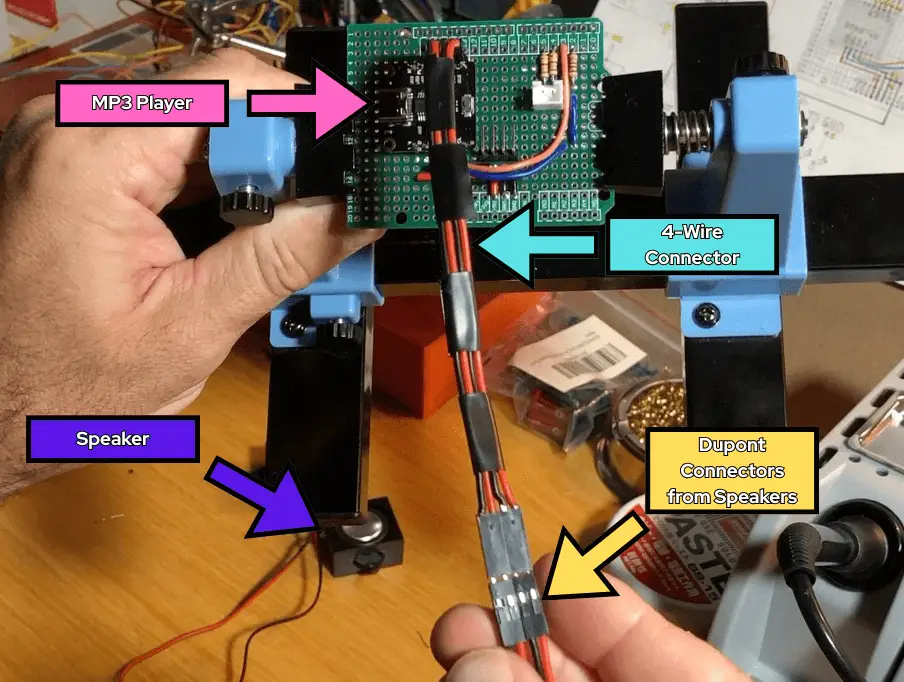
What we have at this point for the process of connecting the two speakers to the MP3 player on the Arduino shield board is:
- Each speaker wire (both red and black) have been extended with 8-inches of extra wire, by splicing and soldering the 8-inch lengths of wire to the speaker wires. These exposed sections of wire were then covered with heat-shrink tubing for protection.
- Each speaker wire end (both red and black) were fitted with a male Dupont pin. Once the red and black wire of a speaker had a male pin, these wires and their pins were inserted into a two-pin Dupont connector housing.
- Then, the two wires of each speaker were taped together for the purposes of keeping everything neat and tidy.
At this point – with our finished male connectors on the ends of both speakers – we can now connect the speakers to the four-wire connector we made in Section I, of Part 6 – the previous section to this one – making sure to match the red and black wires when connecting them.
The four-wire connector has the two four-pin female Dupont connector housings on each end – allowing a connection to the male pins of the speakers, and to the yellow header pins for the R+, R-, L+, and L- pins (for right and left speakers) of the MP3 player we soldered to the Arduino shield board we made in the previous section of this build.
Adding a Header Pin for the PIR Sensor’s OUT Pin
Looking at the HC-SR501 PIR sensor we’re using for this project, we see that after taking the Fresnel lens off, that one of its three pins is for the output line, or OUT. The output pin is 3.3V TTL logic, so it can be used with any microcontroller platform, such as the Arduino we’re using.

I am using a yellow jumper wire with a female Dupont connector attached at both ends to connect from the OUT pin of the PIR sensor, to pin 12 on the Arduino shield board. To connect to pin 12 on the Arduino shield board we’ve made, we need to add a header pin. I am using a 6-pin yellow header pin that will connect to pins 6 to 12 of the Arduino, from the shield board.

So, what I did was solder my yellow header pins on column 3 of the Arduino shield board, making sure that its pins are inline with the through-holes next to pins 6 through 12, reserved for the header pins we’ll put in place to connect to the Arduino, later in the build.
The through-holes for the yellow header pins are connected to the through-holes for the header pins we’ll add later for pins 6 through 12, of the Arduino Uno, via copper pads on the shield board we’ve chosen to use for this project (see image below).

So, for now, we’ll reserve pin 12 for the connection to the OUT pin of the PIR sensor (labeled point E, in the hand-drawn schematic diagram, above). Pins 7 through 9, will be reserved for the connections we’ll make from the gates (G) of the MOSFETs of the daughter board we’ll set up later in the build.
VCC and GND Pins of the PIR Sensor
As for the GND pin of the PIR sensor, we’ll use a black jumper wire with a female Dupont connector attached at both ends to connect from the GND pin of the PIR sensor, to one of the black 90-degree angle header pins we added for the common ground connection on the Arduino shield board we added in the previous section, of this build series. Common ground are the labeled points C, D, and G, in the drawing, below.

As for the VCC pin of the PIR sensor, we’ll use a red jumper wire with a female Dupont connector attached at both ends to connect from the VCC pin of the PIR sensor, to a red header pin we’ll have for the +5 volt supply we’ll set up on our Arduino shield board, next.
Adding a Header Pin for the +5 Volt Supply
As was mentioned earlier, we’re going to need direct access to the +5 volt supply from the Arduino to power the PIR sensor, but our Arduino shield board we’re making to place on top of the Arduino does not currently have any place for the red wire from the VCC of the PIR sensor to connect to.
I could solder the red VCC wire to the Arduino shield board at the +5V supply directly, but I want to be able to disconnect the PIR sensor whenever I need to, so I will solder a 3-pin red header pin to the shield board, and solder those pins together to the +5 supply line we created in the previous section of this build. I chose three pins, so that I may have a couple extra connection points for the +5V supply, if I need them in the future.
I took my 3-pin red header pin and placed it in the through-holes along columns 17, 18, and 19, that are inline with where we had soldered a length of red 22 AWG solid core wire, inline with the VIN pin of the MP3 player, in the previous section of this build. Make sure to solder each pin of this 3-pin red header pin together, and to the +5V supply on the PCB board – we need all 3 pins tied to +5V.

Creating an Extension Wire Connector for the PIR Sensor
At this point in the build, I haven’t fully decided where I want to place the PIR sensor on the owl figure being used for this project, but I would like to give myself enough slack with my wires to be able to reach wherever I need the PIR to go within the cavity of the owl figure, later when I make that decision.
So, what we’ll do is cut another 6 to 8-inch length of red, yellow, and black 24 AWG stranded wire, and strip both ends of each wire about 1/8 of an inch, or so. Next, we’ll attach a female Dupont pin on one end of each colored wire, then take a 3-pin female Dupont connector housing, and place each colored wire with its female Dupont pin end into the housing in order of red, yellow, then black.
Next, we’ll take the other ends of these colored wires, and attach male Dupont pins on each of the ends of the wires. Then, before we place each colored wire with its male Dupont pin end into a 3-pin male Dupont connector housing, we’ll twist the three wires around each other, for better wire management. Now, place the wires with their male Dupont pin ends into the housing in order of red, yellow, then black.
The image below shows a representation of what this three-wire extension connector looks like for the PIR sensor.

Adding Header Pins to Mate to the Arduino Uno
The next order of business is to place the header pins on the Arduino shield board, to be able to mate it to the Arduino Uno we’re using for this project. I took some green header pins – making sure that I had the proper amount of pins to place on each side of the Arduino shield board, to fit into all the through-holes of the female headers of the Arduino Uno when mated together – and soldered them in place onto the Arduino shield board.

Creating the Daughter Board Circuit
At this point of the build, we have our Arduino shield board mostly ready to go – we’ve got the speakers and PIR sensor all wired up and connected to the board. Next we need to move on to creating our secondary PCB board – or daughter board – where we’ll connect all the components for the solenoids and DC motor to it.
There’s a couple of reasons why I’ve had to split the components of this project into the Arduino shield board we’ve been working on and the daughter board we will be working on next, and those reasons are:
- There’s just not enough room on the Arduino shield board to contain all the components for the speakers, PIR sensor, solenoids, and DC motor.
- Having a daughter board divides – for this particular project – provides a good separation of lower and higher power components, and a kind of division between the two separate power supplies we’re using.
- The division of components also creates an easier setup of separate components, as well as giving the ability to provide easier troubleshooting and removing of certain components later, if needed.
The PCB that is being used as the daughter board is a 3CM x 7CM, through-hole perfboard.

Power Rails for Secondary 9V Battery
The first thing to do on the daughter board is to set up the power rails for both the positive and negative supply from the secondary 9V battery supply we’re using to power the solenoids and DC motor. I’m reserving the outer copper pads of the daughter board for the connections from the 9V battery supply, as seen in the image below:
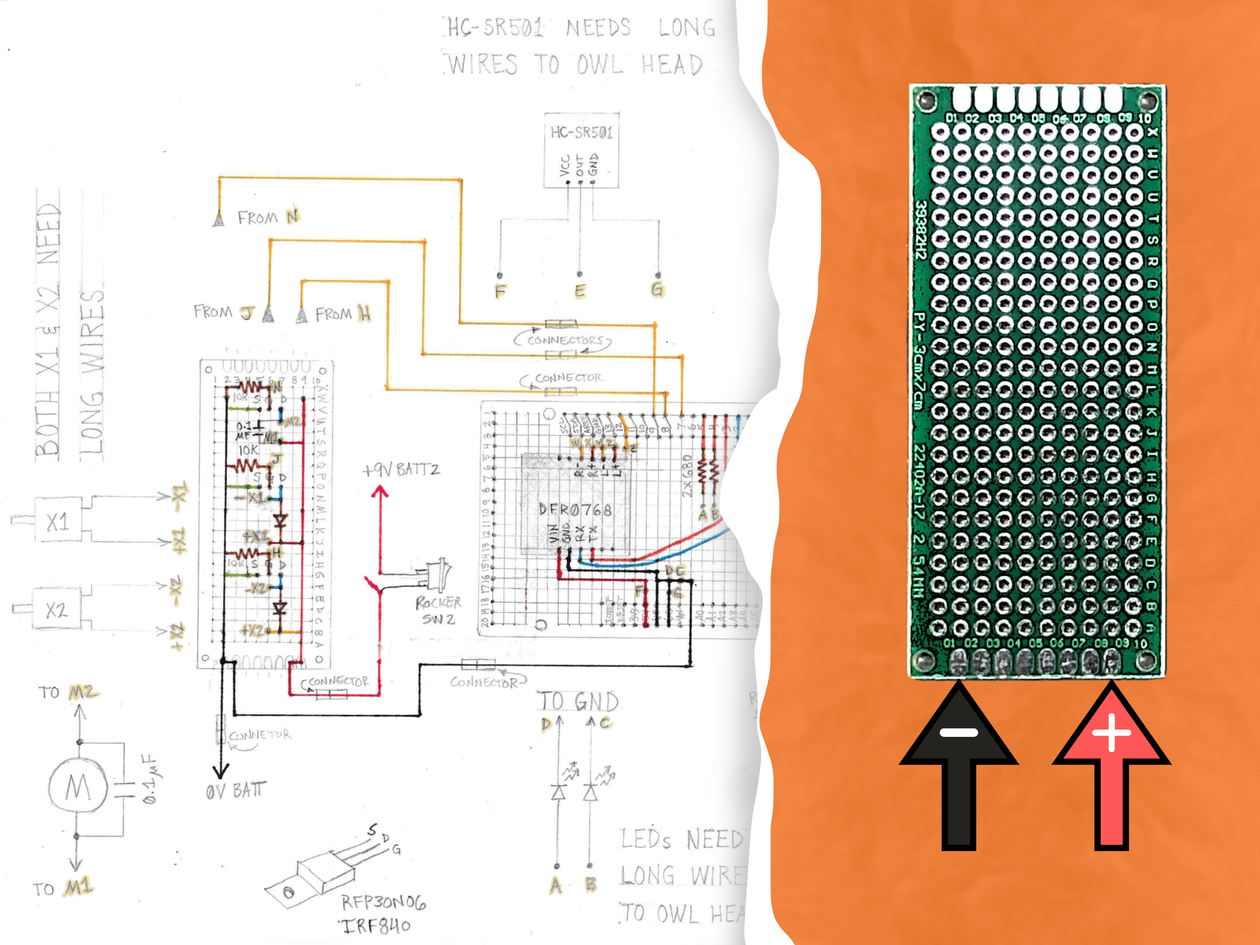
I won’t be making the connections from the 9V battery just yet, but I will start off by adding 22 AWG solid core wire as my power supply rails to the board. We’ll need a length of red and black wire – long enough to reach from row B, to row W of the daughter board – for both the positive and negative supply lines.
The Positive Power Rail
- Cut a length of red 22 AWG solid core wire – about 6 inches – and strip all except about an inch worth of the protective wire sheathing, in the middle of the wire.
- Next, make a 90-degree bend on both ends of the wire you just cut and stripped, making sure that you can place one end of the wire from row B, and the other end of the wire to row W, along column 9 of the daughter board, as seen in the image below.
- Bend the ends of the wires toward the edges of the board to hold the wire in place. Make sure the bent wire coming out of the through-hole from row B can reach the copper pad we’ve designated as the positive, as shown in the image below.
- Then, solder the wire in place at the through-holes at row B, column 9, and at row W, column 9.
- Now, solder the portion of wire that was bent towards the copper pad we designated as the positive, and solder the wire to the pad, as well. This will make a connection from this positive pad, all along our positive wire to column 7, row W.
- Trim any excess wire with your wire cutters once you’re done soldering the positive wire in place on the daughter board.

The Negative Power Rail
- Cut a length of black 22 AWG solid core wire – about 6 inches – and strip all except about an inch worth of the protective wire sheathing, in the middle of the wire.
- Next, make a 90-degree bend on both ends of the wire you just cut and stripped, making sure that you can place one end of the wire from row B, and the other end of the wire to row W, along column 2 of the daughter board, as seen in the image below.
- Bend the ends of the wires toward the edges of the board to hold the wire in place. Make sure the bent wire coming out of the through-hole from row B can reach the copper pad we’ve designated as the negative, as shown in the image below.
- Then, solder the wire in place at the through-holes at row B, column 2, and at row W, column 2.
- Now, solder the portion of wire that was bent towards the copper pad we designated as the negative, and solder the wire to the pad, as well. This will make a connection from this negative pad, all along our positive wire to column 2, row W.
- Trim any excess wire with your wire cutters once you’re done soldering the negative wire in place on the daughter board.

Placing the X2 Solenoid Components on the Daughter Board
We have quite a few components to place on the daughter board, and deciding where to start can be a little overwhelming, but I figure the best place to start is – looking at the top of the daughter board – at the “bottom” of the board, with the diode for the solenoid labeled X2.
Diode for X2 Solenoid
Now we need to start transferring components for the solenoid labeled X2 in the hand-draw schematic diagram from our breadboard prototype circuit we assembled for the solenoids back in Part 5 of this OwlBot build series.
As for the first component to transfer from our breadboard prototype circuit to the daughter board we’re currently working with, we’ll grab the 1N4001 diode that we used as a flyback diode for the solenoid. We’ll place the leads of this diode at the through-holes along column 7, at rows B and F, as seen in the image below.

Once the diode has been soldered in place, we need to extend the connection of the diode’s cathode-side lead to the positive supply wire (positive power rail) we added to the daughter board earlier. This connection is shown on the back-side or bottom-side of the daughter board in the image above, at row B.
MOSFET for X2 Solenoid
Next, I want to take the RFP30N06 MOSFET associated with the 1N4001 diode that I’ve just set on the board for the X2 solenoid. We need to make sure that we place it in the correct orientation, and to do that we can refer to the datasheet of the RFP30N06.
Looking at the MOSFET directly, with its labeling facing towards us, or the drain flange or metal tab with the hole in it facing away from us – we can point out the gate, drain, and source leads, as shown in the image below.

The hand-draw schematic diagram I made shows the order of the pins of the MOSFET as being source, gate, drain (going from left-to-right) – but the pins on the datasheet (and image above) goes gate, drain, source. So, even though it looks like the diode will go to an outer pin or lead of the MOSFET on the hand-draw schematic diagram, in actuality, we will place the MOSFET on the daughter board so that its middle pin (the drain pin) will be inline with the anode of the diode.
So, the middle pin of the RFP30N06 MOSFET is the drain (D) pin, so it needs to be inline with the anode of the diode. I’ve placed the middle pin of the MOSFET inline with the diode at the through-hole of column 7, at row G. The source (S) pin is at column 8, row G – and the gate (G) pin at column 6, row G. Go ahead and solder the MOSFET in place. See image below, under “Jumper Wire for Source Pin of MOSFET for X2 Solenoid”.
10kΩ Resistor at Gate of MOSFET for X2 Solenoid
Now that we have our first MOSFET down on the daughter board, lets transfer the 10kΩ resistor that goes to its gate (G), from the breadboard to the perfboard.
Just as we did when prototyping our circuit on the breadboard, we need to connect the 10kΩ resistor to the gate of the RFP30N06 MOSFET, for the X2 solenoid. I placed one lead of the resistor at the through-hole at column 5, row G – next to the gate (G) pin of the MOSFET – and soldered the resistor lead there. Before trimming the excess lead off the resistor after soldering, I had bent the lead toward the gate pin of the MOSFET, and soldered the resistor lead to the gate to make that connection. Then, I trimmed off any excess with my wire cutters.
I placed the other lead of the resistor at the through-hole at column 1, row G, and soldered the resistor in place on the daughter board. Before trimming the excess lead off the resistor after soldering, I had bent the lead toward the negative power rail we established on the board earlier, and made the connection there by soldering the lead to the solid core wire for our common ground. Then, I trimmed off any excess with my wire cutters. See image below, under “Jumper Wire for Source Pin of MOSFET for X2 Solenoid”.
Jumper Wire for Source Pin of MOSFET for X2 Solenoid
So far, we’ve connected the diode to the drain (D) pin of the MOSFET, we’ve connected the resistor to the gate (G) pin of the MOSFET, now we need to connect the source (S) pin of the MOSFET to the common ground using a jumper wire.
Cut a length of green 24 AWG, solid core wire, that will reach from the source pin of the MOSFET at the through-hole at column 8, row H, to the through-hole at column 1, row H. Solder the green jumper wire at the through-hole at column 8, row H, making sure that you solder the wire to the source (S) pin of the MOSFET. Then, solder the other end of the green jumper wire at the through-hole at column 1, row H, making sure that you solder the wire to the negative power rail we’ve established earlier as our common ground on the daughter board.
All connections we’ve made so far to the daughter board can bee seen in the image representation of what our board should look like at this point in the build, below:

Placing the X1 Solenoid Components on the Daughter Board
Now that we have most of what we need setup for the X2 solenoid, let’s now move on to transferring components for the solenoid labeled X1 in the hand-draw schematic diagram from our breadboard prototype circuit we assembled for the solenoids back in Part 5 of this OwlBot build series.
Diode for X1 Solenoid
Just like we did for the X2 solenoid, our first component to transfer from our breadboard prototype circuit for the X1 solenoid is its 1N4001 diode that we used as a flyback diode for the solenoid. We’ll place the leads of this diode at the through-holes along column 7, at rows J and N, as seen in the image below.

Once the diode has been soldered in place, we need to extend the connection of the diode’s cathode-side lead to the positive supply wire (positive power rail) we added to the daughter board earlier. This connection is shown on the back-side or bottom-side of the daughter board in the image above, at row J.
MOSFET for X1 Solenoid
Next, I want to take the RFP30N06 MOSFET associated with the 1N4001 diode that I’ve just set on the board for the X1 solenoid. We need to make sure that we place it in the correct orientation, and to do that we can refer to the datasheet of the RFP30N06, just as we needed to for the MOSFET for the X2 solenoid.
Looking at the MOSFET directly, with its labeling facing towards us, or the drain flange or metal tab with the hole in it facing away from us – we can point out the gate, drain, and source leads, as shown in the image for the RFP30N06 MOSFET, above.
The hand-draw schematic diagram I made shows the order of the pins of the MOSFET as being source, gate, drain (going from left-to-right) – but the pins on the datasheet (and image above) goes gate, drain, source. So, even though it looks like the diode will go to an outer pin or lead of the MOSFET on the hand-draw schematic diagram, in actuality, we will place the MOSFET on the daughter board so that its middle pin (the drain pin) will be inline with the anode of the diode.
So, the middle pin of the RFP30N06 MOSFET is the drain (D) pin, so it needs to be inline with the anode of the diode. I’ve placed the middle pin of the MOSFET inline with the diode at the through-hole of column 7, at row O. The source (S) pin is at column 8, row O – and the gate (G) pin at column 6, row O. Go ahead and solder the MOSFET in place. See image below, under “Jumper Wire for Source Pin of MOSFET for X1 Solenoid”.
10kΩ Resistor at Gate of MOSFET for X1 Solenoid
We need to connect the 10kΩ resistor to the gate of the RFP30N06 MOSFET, for the X1 solenoid. I placed one lead of the resistor at the through-hole at column 5, row O – next to the gate (G) pin of the MOSFET – and soldered the resistor lead there. Before trimming the excess lead off the resistor after soldering, I had bent the lead toward the gate pin of the MOSFET, and soldered the resistor lead to the gate to make that connection. Then, I trimmed off any excess with my wire cutters.
I placed the other lead of the resistor at the through-hole at column 1, row O, and soldered the resistor in place on the daughter board. Before trimming the excess lead off the resistor after soldering, I had bent the lead toward the negative power rail we established on the board earlier, and made the connection there by soldering the lead to the solid core wire for our common ground. Then, I trimmed off any excess with my wire cutters. See image below, under “Jumper Wire for Source Pin of MOSFET for X1 Solenoid”.
Jumper Wire for Source Pin of MOSFET for X1 Solenoid
So far, we’ve connected the diode to the drain (D) pin of the MOSFET, we’ve connected the resistor to the gate (G) pin of the MOSFET, now we need to connect the source (S) pin of the MOSFET to the common ground using a jumper wire.
Cut a length of green 24 AWG, solid core wire, that will reach from the source pin of the MOSFET at the through-hole at column 8, row P, to the through-hole at column 1, row P. Solder the green jumper wire at the through-hole at column 8, row P, making sure that you solder the wire to the source (S) pin of the MOSFET. Then, solder the other end of the green jumper wire at the through-hole at column 1, row P, making sure that you solder the wire to the negative power rail we’ve established earlier as our common ground on the daughter board.
All connections we’ve made so far to the daughter board can bee seen in the image representation of what our board should look like at this point in the build, below:

Placing the DC Motor Components on the Daughter Board
Now that we have the MOSFETs for both solenoids set on the daughter board, we have one MOSFET left to add to the circuit – for the DC motor.
MOSFET for DC Motor
We’ll transfer the IRF840 MOSFET from the breadboard prototype circuitry, to the daughter board, and place the gate, drain, and source pins at the through-holes at columns 6, 7, and 8, respectively, along row V. See image below, under “Jumper Wire for Source Pin of MOSFET for DC Motor”.
10kΩ Resistor at Gate of MOSFET for DC Motor
We need to connect the 10kΩ resistor to the gate of the IRF840 MOSFET, for the DC motor. I placed one lead of the resistor at the through-hole at column 5, row V – next to the gate (G) pin of the MOSFET – and soldered the resistor lead there. Before trimming the excess lead off the resistor after soldering, I had bent the lead toward the gate pin of the MOSFET, and soldered the resistor lead to the gate to make that connection. Then, I trimmed off any excess with my wire cutters.
I placed the other lead of the resistor at the through-hole at column 1, row V, and soldered the resistor in place on the daughter board. Before trimming the excess lead off the resistor after soldering, I had bent the lead toward the negative power rail we established on the board earlier, and made the connection there by soldering the lead to the solid core wire for our common ground. Then, I trimmed off any excess with my wire cutters. See image below, under “Jumper Wire for Source Pin of MOSFET for DC Motor”.
Jumper Wire for Source Pin of MOSFET for DC Motor
We’ve connected the resistor to the gate (G) pin of the MOSFET, now we need to connect the source (S) pin of the MOSFET to the common ground using a jumper wire.
Cut a length of green 24 AWG, solid core wire, that will reach from the source pin of the MOSFET at the through-hole at column 8, row W, to the through-hole at column 1, row W. Solder the green jumper wire at the through-hole at column 8, row W, making sure that you solder the wire to the source (S) pin of the MOSFET. Then, solder the other end of the green jumper wire at the through-hole at column 1, row W, making sure that you solder the wire to the negative power rail we’ve established earlier as our common ground on the daughter board.

Adding a JST Connector for the DC Motor
In order to connect the DC motor to the daughter board, we will be using an XH-2W connector socket on the board. Later we’ll add an XH-2Y connector socket to the two wires coming from the DC motor, to be able to plug into the XH-2W connector socket on the board.

The XH-2W connector socket I’m using is angled at 90-degrees. So, taking an XH-2W connector socket, we’ll place the terminals at the through-holes along column 7, at rows S and T. Be sure that you point the connector socket towards rows 8 through 10, so that the DC motor’s wires can be plugged in from the right-side of the board (front/top facing you), as observed in the image representation of the board below.
The XH-2W connector socket represents the points M1 and M2, on the hand-drawn schematic diagram, circled in the image directly below.

Next, we need to make the connections from the connector socket’s terminals to the drain of the IFR840 MOSFET, and to the positive power supply wire. First, solder a connection from the pin of the XH-2W connector socket, at row T, to the drain (D) pin of the MOSFET, at row V, column 7.
Next, using an orange 22 AWG solid core jumper wire, solder one end of the wire at the through-hole at row R, column 7 – right next to the second pin of the XH-2W connector socket, at row S. Solder the two points together to make a connection between the two.
Then, solder the other end of the orange jumper wire at the through-hole at row Q, column 10 – continuing this connection to the positive supply wire by soldering from the jumper wire at row Q, column 10, directly to the positive supply wire.
All connections we’ve made so far to the daughter board can bee seen in the image representation of what our board should look like at this point in the build, below:

Soldering the Capacitor to the Terminals of the DC Motor
In “How to Make an OwlBot: The Bird Intimidator – Part 5: Mechanical Movement,” we placed a 100 nano-farad (0.1µF) shunt capacitor across the terminals of the DC motor, as part of the prototyping process on the breadboard. We still have not yet soldered the capacitor across the terminals. So, we need to do this step, next.
Just as was discussed on Step 0, of the Scrubberbot project and was shown in the video for Soldering Disc Capacitors Across DC Motor Terminals, we’ll perform the same process as shared on those resources to solder the capacitor across the terminals of the DC motor for the OwlBot circuit. Feel free to click the links to those resources, if you need guidance for this part of the build process. Otherwise, all you need to do is to solder the terminals of the capacitor directly to the terminals of the motor.
Adding More Connector Sockets to the Daughter Board
Up to this point in the build we have done quite a bit in preparation of getting the components we need for the solenoids and DC motor soldered onto the daughter board. Earlier, we added a JST connector socket to the board to be able to plugin the DC motor, once we add an XH-2Y connector to the wires of the DC motor, later in the build.
We want to also be able to connect the two solenoids to the daughter board, using JST connector sockets, that represent the points of connection for the solenoids, X1 and X2, as shown below in the hand-drawn schematic diagram.

We also need to have our connection points from each of the gate (G) pins of each MOSFET, to have its own connector socket, as well. We’ll use a 3-pinned connector socket, that will represent the points of connection for each gate pin – those are the points labeled H, J, and N, on the hand-draws schematic diagram.
Connector Socket for X2 Solenoid
Taking an XH-2A connector socket, we’ll place it at the through-holes at rows C and D, along column 4. This connector socket is to be able to plugin the solenoid labeled X2 in the drawing, across the diode going to the drain (D) of the first RFP30N06 MOSFET, we placed along row G. This connector socket represents the points labeled +X2 and -X2, on the hand-drawn schematic diagram.

Next, we need to make the connections from the pins of the connector socket across the diode. Take two small lengths of yellow 22 AWG solid core wire to make as jumper wires. Use one jumper wire to go from the through-hole at row E, column 4 – next to the pin of the connector socket at row D, column 4 – to the through-hole hole at row F, column 6 – next to the anode lead of the diode at the through-hole at row F, column 7.
Solder the jumper wire in place, and make the proper connections in soldering to allow a path for current flow from the diode’s anode lead at row F, column 7, through the jumper wire to the pin of the connector socket at row D, column 4.
Now, use the second yellow jumper wire to go from the through-hole at row B, column 4 – next to the pin of the connector socket at row C, column 4 – to the through-hole hole at row B, column 6 – next to the cathode lead of the diode at the through-hole at row B, column 7.
Solder the second jumper wire in place, and make the proper connections in soldering to allow a path for current flow from the diode’s cathode lead at row B, column 7, through the jumper wire to the pin of the connector socket at row C, column 4.

Connector Socket for X1 Solenoid
Taking another XH-2A connector socket, we’ll place it at the through-holes at rows K and L, along column 4. This connector socket is to be able to plugin the solenoid labeled X1 in the drawing, across the diode going to the drain (D) of the second RFP30N06 MOSFET, we placed along row O. This connector socket represents the points labeled +X1 and -X1, on the hand-drawn schematic diagram.
Next, we need to make the connections from the pins of the connector socket across the diode. Take two small lengths of yellow 22 AWG solid core wire to make as jumper wires. Use one jumper wire to go from the through-hole at row M, column 4 – next to the pin of the connector socket at row L, column 4 – to the through-hole hole at row N, column 6 – next to the anode lead of the diode at the through-hole at row N, column 7.
Solder the jumper wire in place, and make the proper connections in soldering to allow a path for current flow from the diode’s anode lead at row N, column 7, through the jumper wire to the pin of the connector socket at row M, column 4.
Now, use the second yellow jumper wire to go from the through-hole at row J, column 4 – next to the pin of the connector socket at row K, column 4 – to the through-hole hole at row J, column 6 – next to the cathode lead of the diode at the through-hole at row J, column 7.
Solder the second jumper wire in place, and make the proper connections in soldering to allow a path for current flow from the diode’s cathode lead at row J, column 7, through the jumper wire to the pin of the connector socket at row K, column 4.

Connector Socket for the Gate Pins of Each MOSFET
Looking at the hand-drawn schematic diagram, we see that we have our connections from the MOSFETs – labels H, J, and N – going to pins 7, 8, and 9, of the Arduino shield board, which fits on top of the Arduino Uno, making direct connections to the pins 7, 8, and 9, of the Arduino.
To make these connections from the daughter board to the Arduino shield board we’ve made, we’ll use the help of an XH-3A connector socket on the daughter board and a 3-wire connector wire we’ll make, later in the build. We’ll use the XH-3A connector socket to make our connections from each gate (G) of the MOSFETs on the daughter board, to the three pins of the connector socket.

Taking an XH-3A connector socket, we’ll place it and solder it at the through-holes at rows R, S and T, along column 3. As stated earlier, this connector socket is to be able to make the connections from each gate (G) of the MOSFETs on the daughter board, to the three pins of the connector socket. This connector socket represents the points labeled H, J, and N, on the hand-drawn schematic diagram.

Next, we need to make the connections from the pins of the connector socket to the gates of each of the MOSFETs. We’ll need to take 3 varying lengths of yellow 22 AWG solid core wire to make as jumper wires. Use one jumper wire to go from the through-hole at row R, column 4 – next to the pin of the connector socket at row R, column 3 – to the through-hole hole at row H, column 5 – next to the 10kΩ resistor lead at row G, column 5, that’s connected to the gate (G) lead of the RFP30N06 MOSFET, at row G, column 6.
Solder the jumper wire in place, and make the proper connections in soldering to allow a path for current flow from the pin of the XH-3A connector socket at row R, column 3, to the connection on the board between the gate (G) lead of the RFP30N06 MOSFET, at row G, column 6, and the resistor lead at row G, column 5.

Now, use another yellow jumper wire to go from the through-hole at row S, column 4 – next to the pin of the connector socket at row S, column 3 – to the through-hole hole at row P, column 5 – next to the 10kΩ resistor lead at row O, column 5, that’s connected to the gate (G) lead of the RFP30N06 MOSFET, at row O, column 6.
Solder the jumper wire in place, and make the proper connections in soldering to allow a path for current flow from the pin of the XH-3A connector socket at row S, column 3, to the connection on the board between the gate (G) lead of the RFP30N06 MOSFET, at row O, column 6, and the resistor lead at row O, column 5.

Finally, take the third yellow jumper wire to go from the through-hole at row T, column 4 – next to the pin of the connector socket at row T, column 3 – to the through-hole hole at row U, column 5 – next to the 10kΩ resistor lead at row V, column 5, that’s connected to the gate (G) lead of the IRF840 MOSFET, at row V, column 6.
Solder the jumper wire in place, and make the proper connections in soldering to allow a path for current flow from the pin of the XH-3A connector socket at row T, column 3, to the connection on the board between the gate (G) lead of the IRF840 MOSFET, at row V, column 6, and the resistor lead at row V, column 5.

Video Build of OwlBot: Part 6 (Section II)
Overview
At this point of the project, we’ve created the daughter board for the Arduino shield-board we created in Section I of Part 6, of this build series. The daughter board holds the components for the solenoids and DC motor for the OwlBot.
We added connectors to the board to allow for easy connection and removal of the solenoids and motor, if needed in the future. We also added a connector for each gate of the MOSFETs on the daughter board to connect to their dedicated pins on the Arduino Uno from the shield board we made.
The design of these two boards are to allow for easy connection and removal of devices, such as the solenoids, DC motor, speakers, or LEDs if such devices need replacement or if customization is needed for the OwlBot in the future.

What’s Next?
Now that we have the Arduino shield board and its daughter board mostly done, we still need to perform the following tasks to finish up the circuitry for this build:
- Make the connections for the secondary 9V power supply (6 AA battery pack) to the daughter board, to power the solenoids and DC motor.
- Create the 3-wire connector that will plug into the connector socket we just installed on the daughter board for the gate pins of each MOSFET.
- Add switches to both power supplies to have ON/OFF control for each.
- Splice more wire to the solenoids and DC motor wires (to add length to the wires), and add connectors to the ends of those wires.
These tasks will be done in Section III, for Part 6, of this OwlBot build series. We should have all the electronics working and ready to go after that – ready for testing and to finally be placed inside our owl figure. After that, we can start placing the electronics in our owl figure and do the finishing touches to complete this project. We may finally have a body for the OwlBot!
There’s more for us to accomplish, so hang in there because we’re that much closer to finishing this project.
Thank you for participating in this project. We hope that you have enjoyed the build thus far. Let us know by giving a comment in the comments section below. Share the link to your friends and family. Let them know how much you’ve enjoyed the process of prototyping the OwlBot!
