How to Make an OwlBot: The Bird Intimidator – Part 6 (Section 3): PCB Circuit Build
| Project Name: | OwlBot |
| Project Description: | In this section of Part 6, we create the connectors we need to connect the OwlBot’s components to the Arduino shield board and daughter-board. |
| Project Difficulty: | Moderate |
| Project Note: | For this part of the project we will be using a soldering iron and heat-gun. Use caution when handling hot items. |
Introduction
In this part of the project we’re going to be performing the third section of the sixth step of what will eventually be the OwlBot. The OwlBot will be a device that can be used as a bird intimidation tool to scare away pesky birds in the yard, around the house or barn, at restaurants, or in trees, bushes, and gardens. Hence, the phrase, “The Bird Intimidator”.

The OwlBot (a.k.a. “The Bird Intimidator”) we’ll be making will be done in several parts. The OwlBot is an ambitious project. When complete, the OwlBot will sense motion. When motion is detected, the OwlBot should make owl sounds, perform varying movements, and flash its red eyes to intimidate and scare away pests.
To put together all these tasks in one page would be too long and cumbersome, so we’ve decided to split each process we want the OwlBot to do into easy to accomplish chunks or parts as we continue on our goal to complete the OwlBot.

This is Part 6 (Section III)
This is the third section of part six. The sixth part of the OwlBot project has involved us transferring some of our prototype circuit from the breadboard to a more permanent prototype PCB board to be placed inside our owl figure, later in the build process. The following are what we’ve done so far in Part 6 of this build, in Sections I and II:
- We created a hand-drawn PCB schematic diagram to help as a visual aid when transferring the components from the breadboard prototype circuit to the PCB.
- Shared the parts list and tools used for Section I of Part 6, of this build.
- Began soldering components to the Arduino prototype shield board used for this project. The following are what was done up to this point, for Part 6:
- Made positive and negative supply connections.
- Added the MP3 player module to the shield board.
- Added the resistors for the LEDs and RX pin of the MP3 player.
- Made connections to the RX and TX pins of the MP3 player.
- Added connectors and header pins to the shield board.
- Assembled a 4-wire connector for the speakers.
- Assembled the wire connectors for the LEDs.
- Made connections for the speakers
- Added a header pin for the PIR sensor
- Added header pins to mate to the Arduino
- and we created a daughter-board that will hold the connections for the DC motor, solenoids, and power from the secondary power supply.
Next, we’ll need to create several connector cables to be able to connect the DC motor and solenoids to the daughter-board. We’ll also need to create a connector cable for the MOSFETs to be connected to the pins of the Arduino we’ve programmed to. Finally, we’ll add some switches to our circuit to control the ON/OFF switching to both the Arduino and to the devices connected to our daughter-board.

Goal of Part 6 (Section III) of the OwlBot Project
Our goal by the end of this section is to have all of the final connections made to our PCB prototype circuit so that we’ll be ready to transfer it all into the owl figure — therefore, finishing this project. After this section, it is the plan to have one more final part added to this long, drawn out series, finally putting an end to the build and having a completely working OwlBot.
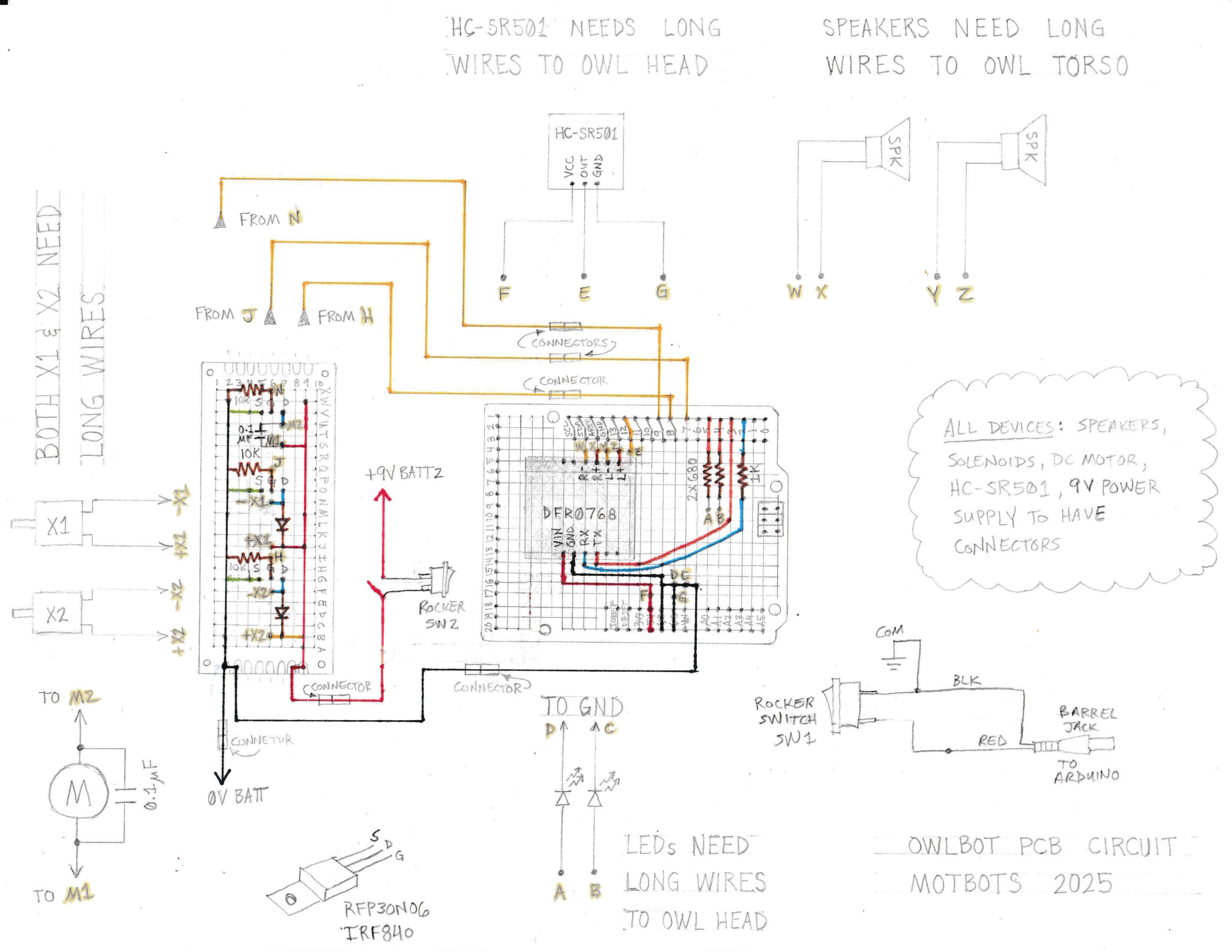
The Hand-Drawn Schematic Diagram for Reference
Below, is the hand-drawn schematic diagram that was made back in Part 6 – Section I, of this build. We’ll use it as a visual aid that we can refer to when making our connections to the PCB boards we’re using for this project. Click the image to download it and save it.
Let’s Be Methodical
I like to be very methodical about things, so we’ll go step-by-step — in detail — on the entire build of this project: the parts we’ll need, why we’re using them, how to connect them, how they work, and more! First, we’ll start with the following parts list for the items we’ll need for this part of the project:
Parts and Tools List
(This parts list is a continuation of the previous parts lists of the OwlBot project, and may contain parts already listed from before.)
| Item | Description |
| Crimping Tool JST Connector Kit | This is the exact kit that I used for this project. This kit includes 29 types of JST-XH/SM/SYP 2.5mm Connectors, with 32-20 AWG Ratchet Crimping Pliers and Wire Strippers — everything you’d need to make the types of connections that I did. |
| Wire Connectors with Crimping Tool | I used spade connectors to connect the wires of the switches to the power supplies. |
| 20 AWG Stranded Wire | Used for the switch wires. |
| 24 AWG Stranded Wire | Used to make connector wires. |
| ON/OFF Rocker Switch SPST | I used two simple rocker switches to control the power to the Arduino and the power to the daughter-board. |
| Heat Shrink Tubing | We’ll use these to protect some of the soldered connections we’ll make. |
| Heat Shrink Gun | We’ll use this device for heat shrink tubing. |
Adding a Connector to the Wires of the DC Motor
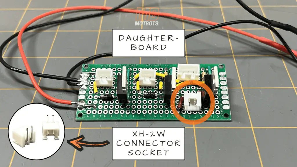
In Section II, of Part 6, we created a daughter-board or second PCB prototype board to hold the components of the circuit that controlled the DC motor and solenoids — like some resistors, diodes, and MOSFETs. To allow us to easily connect and disconnect the motor and solenoids to that board, we used varying types of connector sockets that we soldered to the board.
One of the connector sockets that we used for connecting the DC motor to the daughter-board was a XH-2W connector socket.
The thing is though, the two wires on my DC motor were too short to connect to the XH-2W connector socket and reach anywhere I needed it to within the owl figure we’re using for this project — I did not have enough slack in the wire to place the motor far enough away from the board to its final location.
What I decided was best to do was to make some sort of extension wire for the DC motor so that I could place the motor wherever I desired it to be on the owl figure and have plenty of length in wire to easily connect to the motor’s connector socket on the daughter-board.
What I did was add a SYP-2Y connector to the ends of both the red and blue wires coming from the DC motor.
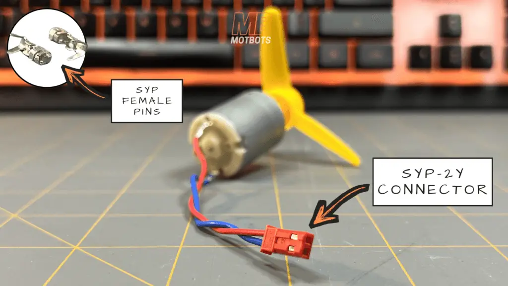
I added a SYP Female Pin to each of those wires using a crimper tool, to then insert them into the red plastic SYP connector you see in the image above. You can see that I also twisted the red and blue wires of the DC motor before adding the SYP connector for better wire management.
Making an Extension Connector Wire Plug for the DC Motor
The wires on my DC motor were only about 3 inches or so long, so I wanted to give myself plenty of slack to be able to reach inside the owl figure I’m using for the OwlBot to connect to the daughter board.
Once I had the SYP-2Y connector attached to the ends of the red and blue wires of the DC motor, I was ready to make the extension wire plug for it to reach wherever I needed it to within the owl figure.
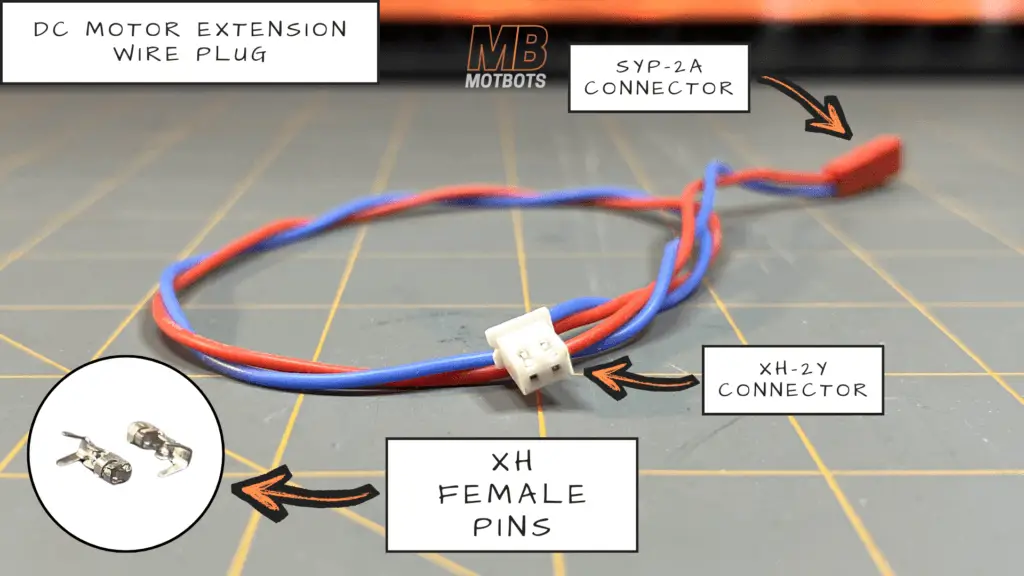
To keep with the same color wires of the DC motor, I cut two equal lengths of red and blue 24 gauge stranded wire — about 10-12 inches in length.
Since I had used a SYP-2Y connector with SYP Female Pins on the ends of the wires of the DC motor, I needed to have a SYP-2A connector socket at the ends of the red and blue 24 gauge stranded wires I cut to length.
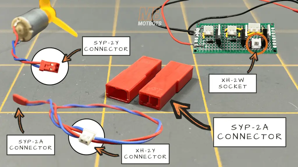
As for the other ends of the red and blue 24 gauge stranded wires, I needed to add a XH-2Y connector to their ends to be able to connect the DC motor to the XH-2W socket we soldered to the daughter-board for it.
What I did was add the XH Female Pins to the opposite ends of those red and blue extension wires I cut to length. I then placed them into the XH-2Y connector socket which allowed me to connect the extension cable to the 90-degree XH-2W socket we soldered to the daughter board in the previous section of this build.
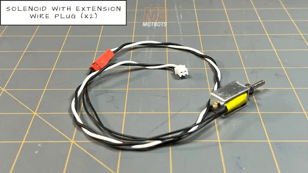
Adding a Connector to the Wires of each Solenoid
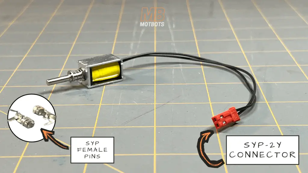
Just as my DC motor wires were too short, both solenoids had two black wires that were too short. I needed to give myself plenty of slack for the solenoid wires to be able to reach inside the owl figure I’m using for the OwlBot to connect to the daughter board.
I made the same type of connections at the ends of each of the solenoid’s wires as I did with the DC motor — I added a SYP Female Pin to each of those wires using a crimper tool, to then insert them into a red plastic SYP-2Y connector (for both solenoids).
Making Extension Connector Wire Plugs for the Solenoids
Once I added a SYP-2Y connector to the ends of each solenoid’s paired wires, I then made an extension wire plug for each of the solenoids. I took two equal lengths of black and white 24 gauge stranded wire — about 10-12 inches in length.
Since I had used a SYP-2Y connector with SYP Female Pins on the ends of the wires of both pairs of the solnoid’s wires, I needed to have a SYP-2A connector socket at the ends of the black and white 24 gauge stranded wires I cut to length.
As for the other ends of the black and white 24 gauge stranded wires, I needed to add a XH-2Y connector to their ends to be able to connect the solenoids to their XH-2A sockets we soldered to the daughter-board for them.
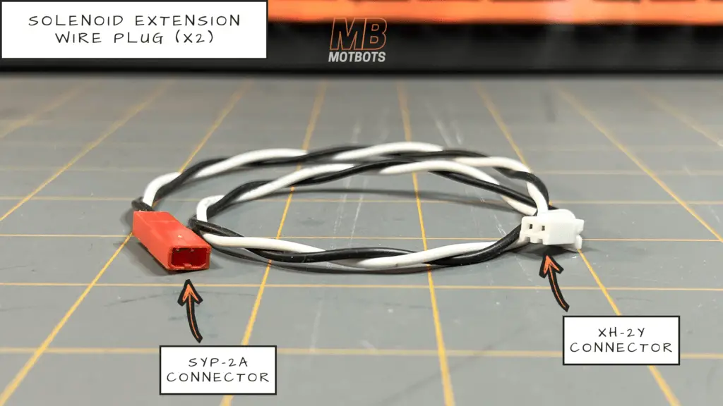
What I did was add the XH Female Pins to the opposite ends of those black and white extension wires I cut to length. I then placed them into the XH-2Y connector socket which allowed me to connect the extension cable to the XH-2A sockets we soldered to the daughter board in the previous section of this build.
Once this was done, I was then able to connect each solenoid to the daughter board using the extension wire plugs I made for each solenoid.
Making a Connector Wire Plug for the MOSFETs
If you remember in the previous section of this project, we added three MOSFETs to the daughter board — and you may also remember that we put a XH-3A connector socket on that daughter board where we connected each of the pins of that connector socket to each gate of the MOSFETs:
- one MOSFET was for solenoid X1
- another MOSFET was for solenoid X2
- and the other MOSFET was for the DC motor
I had labeled the points of contact of those gates on the hand-drawn schematic diagram as:
- point H
- point J
- and point N
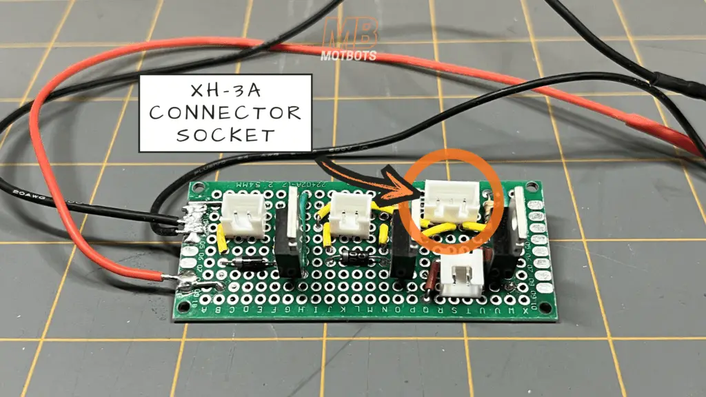
to be able to connect the gates of the MOSFETs to the Arduino shield board — to pins 7, 8, and 9 of the Arduino.
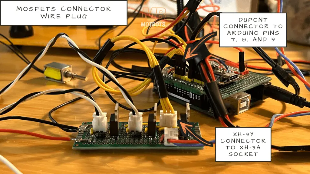
I needed to create a connector wire plug to go from the XH-3A connector socket of the daughter board to the pins 7, 8, and 9 on the Arduino shield board we created in Part 6, Section I of this project series. What I did was cut three equal lengths of yellow 24 gauge stranded wire — about 6 inches in length — and stripped each of their ends to expose the stranded wire.
I connected a XH Female Pin to one end of each of those yellow wires — and then inserted each into a XH-3Y connector socket — this socket for the three yellow wires will allow me to connect them to the connector socket on the daughter board for the gate connections to the MOSFETs.
As for the opposite ends of those three yellow wires, I attached a female Dupont pin to each wire end, then I inserted each of those female Dupont pin ends into a three terminal Dupont connector socket. Doing this allowed me to connect the other end of this connector wire plug to the pins on the Arduino shield board we’re using to bridge the connection from the gates of the MOSFETs on the daughter board to the pins 7, 8, and 9 of the Arduino.
Adding Switches to the Circuit
To be able to control the power supplies of the OwlBot circuit, I used two SPST rocker switches:
- one switch to control the ON/OFF switching of the 9V battery power supply for the Arduino Uno and the components attached to it — the LEDs, PIR sensor, speakers, and MP3 player
- one switch to control the ON/OFF switching of the 9V supply consisting of 6AA batteries for the daughter-board and the components attached to it — the DC motor and solenoids
9V Battery Supply Switch
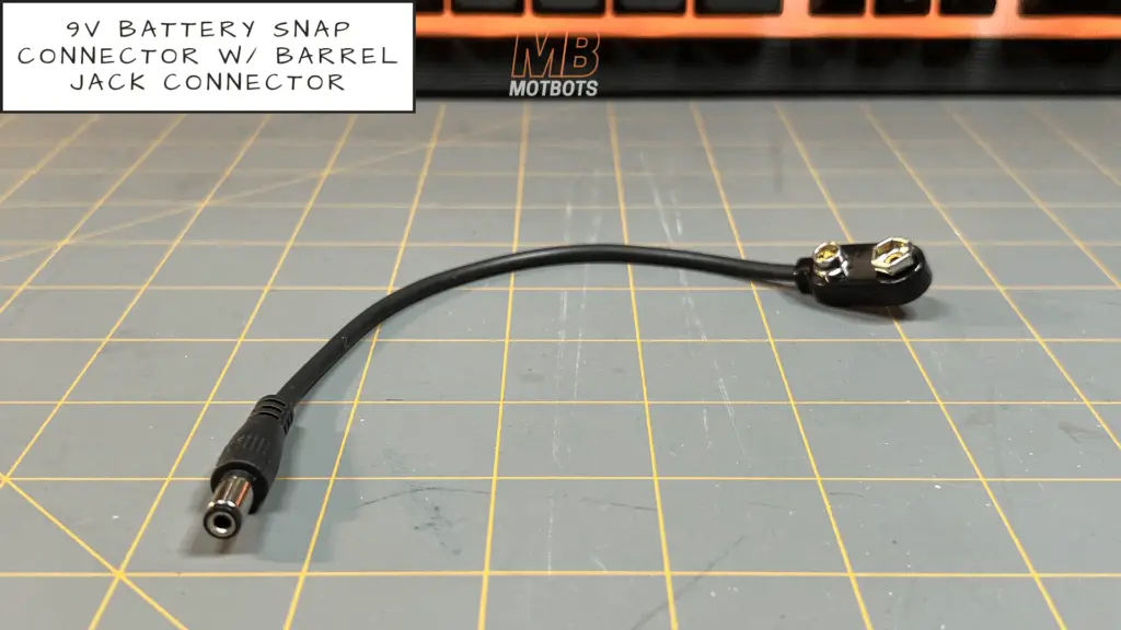
Let’s start with the switch for the 9V battery. The Arduino Uno allows the use of a supply voltage through a barrel jack socket on the board. What I needed was a connector to attach to the 9V battery terminals and to the barrel jack socket of the Arduino.
I took a 9V battery snap connector that had a 3.5mm barrel jack on its end to make the connection from the 9V battery to the Arduino board for powering the Arduino. To be able to add a switch to this connector, I had to cut it in half. Once cut in half, this exposed the red and black wires of the connector.
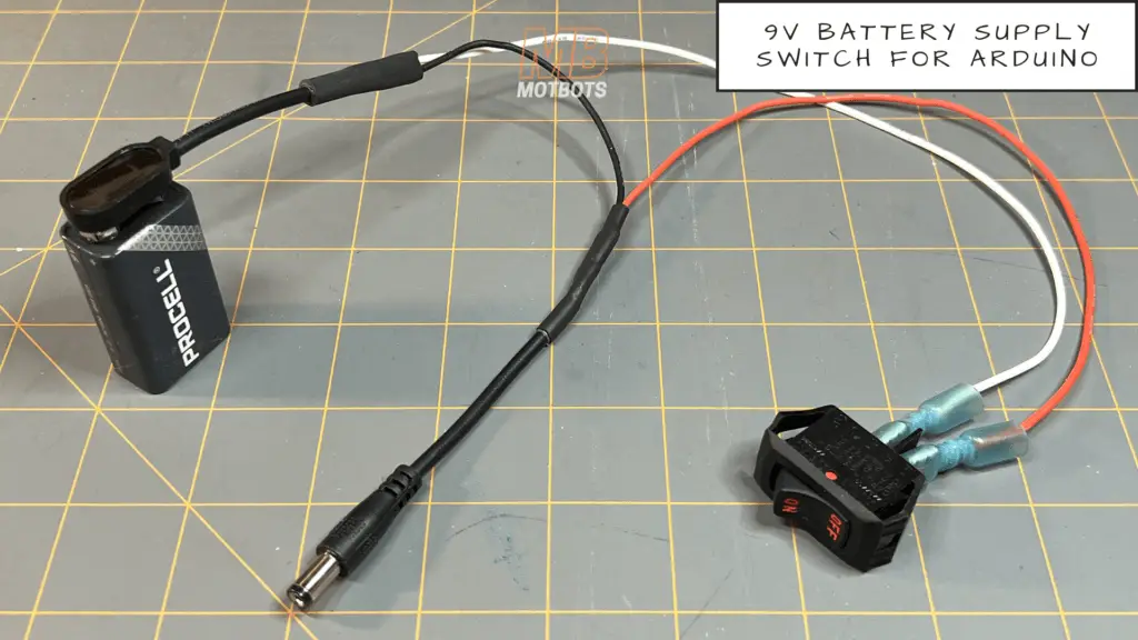
What I did to tap into the wires of the 9V battery connector I cut in half was to solder one end of a 10-12 inch piece of white 20 gauge stranded wire to the exposed red wire from the battery snap connector half of the 9V battery connector. I then made a mechanical connection to the other end of that white wire using a crimping tool and spade connector to be able to attach that end of the white wire to one of the terminals of a rocker switch.
Next, I took a 10-12 inch length of red 20 gauge stranded wire to solder one end of it to the exposed red wire from the barrel jack half of the 9V battery connector. I then made a mechanical connection to the other end of that red wire using a crimping tool and spade connector to be able to attach that end of the red wire to the other terminal of the rocker switch.
The last thing I needed to do for this switch and connector setup was to reconnect the black ground or negative supply wires of the 9V battery connector. I used a 5-6 inch length of black 20 gauge stranded wire to solder one end of it to the exposed black wire of the 9V battery snap connector. I then soldered the other end of the black 20 gauge stranded wire to the exposed black wire of the barrel jack. I also made sure to add heat shrink tubing to all the wires to be soldered together before soldering them.
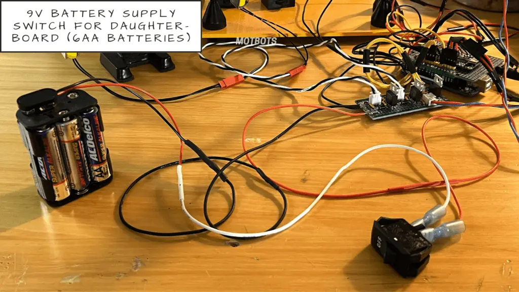
9V (6 AA Battery) Supply Switch
Moving on to the switch for the 9V battery supply consisting of 6 AA batteries, I performed a similar setup as I did for the 9V battery supply switch for the Arduino.
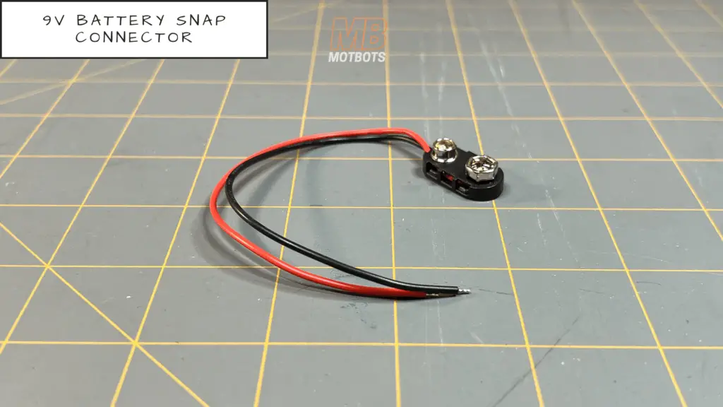
If you remember, the secondary battery supply that we used to power the daughter-board consists of 6 AA batteries installed in a 6 AA battery housing with 9V battery snap connector terminal. The 9V battery snap connector terminal allows us to use another type of 9V battery snap connector — one that just has two exposed wires coming from it: a red wire and a black wire.
I soldered one end of a 10-12 inch piece of white 20 gauge stranded wire to the red wire from the battery snap connector. I then made a mechanical connection to the other end of that white wire using a crimping tool and spade connector to be able to attach that end of the white wire to one of the terminals of a rocker switch.
Next, I took a 6-8 inch length of red 20 gauge stranded wire to solder to the end of the red wire we soldered coming from the daughter-board connected to our positive power supply connection. I then made a mechanical connection to the other end of the red 20 gauge stranded wire wire using a crimping tool and spade connector to be able to attach that end of the red wire to the other terminal of the rocker switch.
The last thing I needed to do for this switch and connector setup was to connect the black ground or negative supply wire of the 9V battery snap connector to the black wire we soldered coming from the daughter-board connected to our negative power supply connection. I used a 5-6 inch length of black 20 gauge stranded wire to solder one end of it to the black wire of the 9V battery snap connector. I then soldered the other end of the black 20 gauge stranded wire to the black wire coming from the daughter-board connected to our negative power supply connection. I also made sure to add heat shrink tubing to all the wires to be soldered together before soldering them.
Video: How to Make an OwlBot: The Bird Intimidator – Part 6 (Section III): PCB Circuit Build
Overview
At this point in the project we’ve completed the transfer of all components from our breadboard prototype circuit to our Arduino shield board and daughter-board we’ve made within the last couple of sections of Part 6 of this OwlBot project series.
We’ve made the connectors we needed to connect the components we’re using for the OwlBot to sense motion, flash LEDs, make owl sounds, and provide varying forms of movement. The only thing left for us to do is to place all of our components and PCB prototype boards within the owl figure, and to create the wings for it for the solenoids to move them about.
What’s Next?
We’re getting so close to the end of this long drawn-out project — every step of the process so far has been a fun learning experience though. The last things we need to do is the modifications of the owl figure to be able to place the components and PCB prototype boards within it, and we need to still create the wings for the OwlBot for the solenoids to move them about.
These last few tasks will be done in Part 7, of this OwlBot build series. We should have the OwlBot finished then, with all the electronics working and the OwlBot ready for testing to finally be placed outdoors to scare away those pesky critters.
There’s a little more for us to accomplish yet, so hang in there because we’re that much closer to finishing this project.
Thank you for participating in this project. We hope that you have enjoyed the build thus far. Let us know by giving a comment in the comments section below. Share the link to your friends and family. Let them know how much you’ve enjoyed the process of building the OwlBot!
