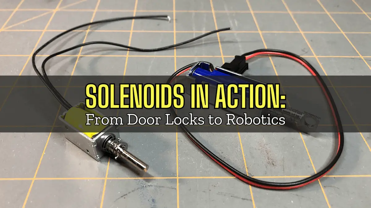
Solenoids in Action: From Door Locks to Robotics
What is a Solenoid?
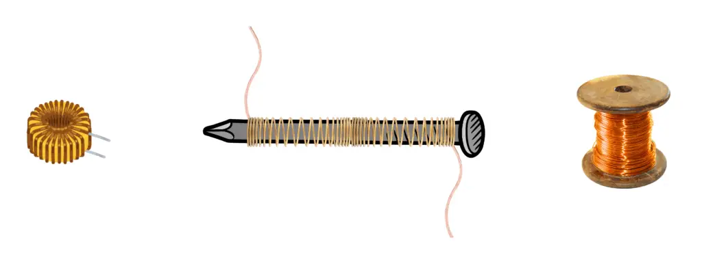
A solenoid is a type of electromagnet that consists of a helical coil of wire. Its length is significantly greater than its diameter. Think of a 10ft length of magnet wire and then wrapping that magnet wire around a 16-penny nail. The width of the wound wire along the nail is much less than the length of the wire itself.
The conditions of a helical coil of wire allows it to generate a controlled magnetic field when an electric current passes through it. This magnetic field can create linear motion, making solenoids useful in various applications where mechanical movement is required.
Quick Physics!
To be honest, most everything we’ll talk about in developing our understanding of solenoids will involve some physics. So, our discussion of physics won’t be that quick, but we won’t go that deep into the physics either, so don’t worry!
Fleming’s Right-Hand Rule
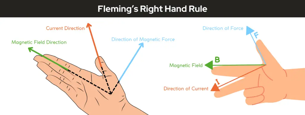
Fleming’s Right-Hand Rule is a simple and practical method used to determine the direction of induced current when a conductor moves through a magnetic field. The rule is commonly applied in the context of electromagnetic induction, such as in electric generators.
How It Works:
- Position Your Right Hand:
- Stretch your thumb, index finger, and middle finger perpendicular to each other (forming a 90° “L” shape).
- What Each Finger Represents:
- Thumb: Represents the direction of the motion of the conductor (relative movement of the conductor or magnetic field).
- Index Finger: Represents the direction of the magnetic field (from North to South).
- Middle Finger: Represents the direction of the induced current (conventional current flow, positive to negative).
Key Applications:
- Used in electric generators to determine the direction of current generated.
- Helps understand the interaction between motion, magnetic fields, and induction.
Mnemonic to Remember:
Think of the rule as “FBI“:
- F = Force or Motion (Thumb),
- B = Magnetic Field (Index Finger),
- I = Induced Current (Middle Finger).
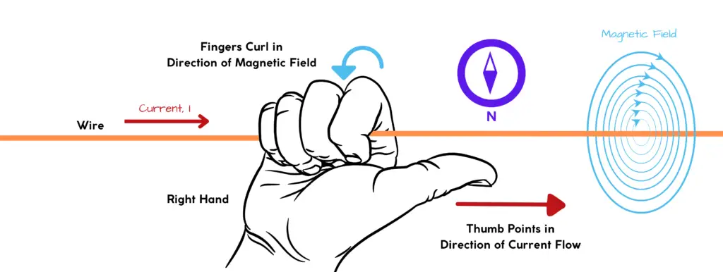
Curled Right-Hand Rule
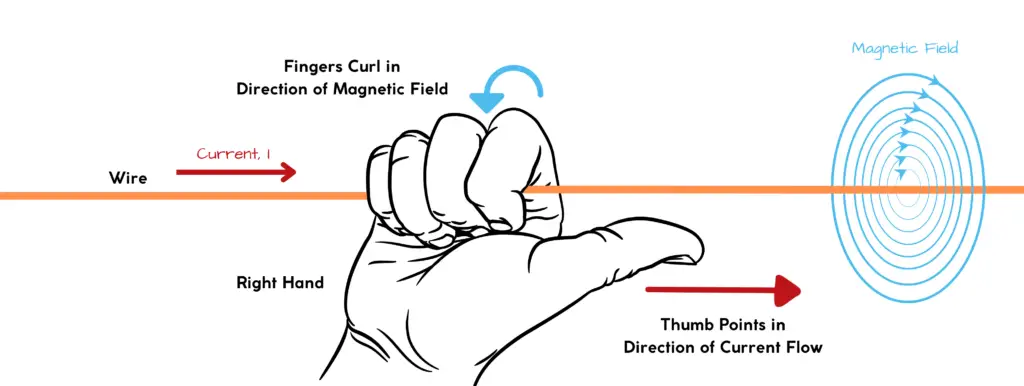
The curled right-hand rule determines the direction of the magnetic field created by a current-carrying conductor.
How It Works:
Point the thumb of your right hand in the direction of the current, and curl your fingers around the conductor. The direction in which your fingers curl represents the direction of the magnetic field lines around the conductor.
When to Use The Right-Hand Rules
Imagine a wire moving through a magnetic field:
- Use Fleming’s Right-Hand Rule to determine the direction of the induced current in the wire.
- Then, use the Curled Right-Hand Rule to find the direction of the magnetic field created by this induced current around the wire.
These rules complement each other and are essential for understanding electromagnetic phenomena like electric generators, motors, and in our case – solenoids.
Permanent Magnets
A permanent magnet is a material that generates a magnetic field on its own, without needing an external power source or electrical current. This magnetic field is caused by the alignment of tiny magnetic domains within the material.
Within each tiny magnetic domain, the magnetic moments (tiny magnetic fields created by electron movement) are aligned in the same direction. In non-magnetic materials, these domains are randomly oriented, canceling each other out.
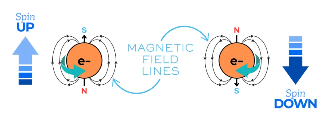
Electrons have a property called spin, which generates a tiny magnetic field. In most materials, electrons pair up with opposite spins, canceling out their magnetic effects. In magnetic materials, many unpaired electrons have their spins aligned, creating a net magnetic field across the material.
If you’re interested in knowing more of the fine details of the topic of magnetic moments and how electron spin ties into magnetism, I highly recommend that you watch this video here.
The problem with permanent magnets is that they cannot be easily “turned off”, meaning they would always be attracting ferrous materials.
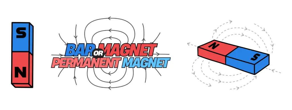
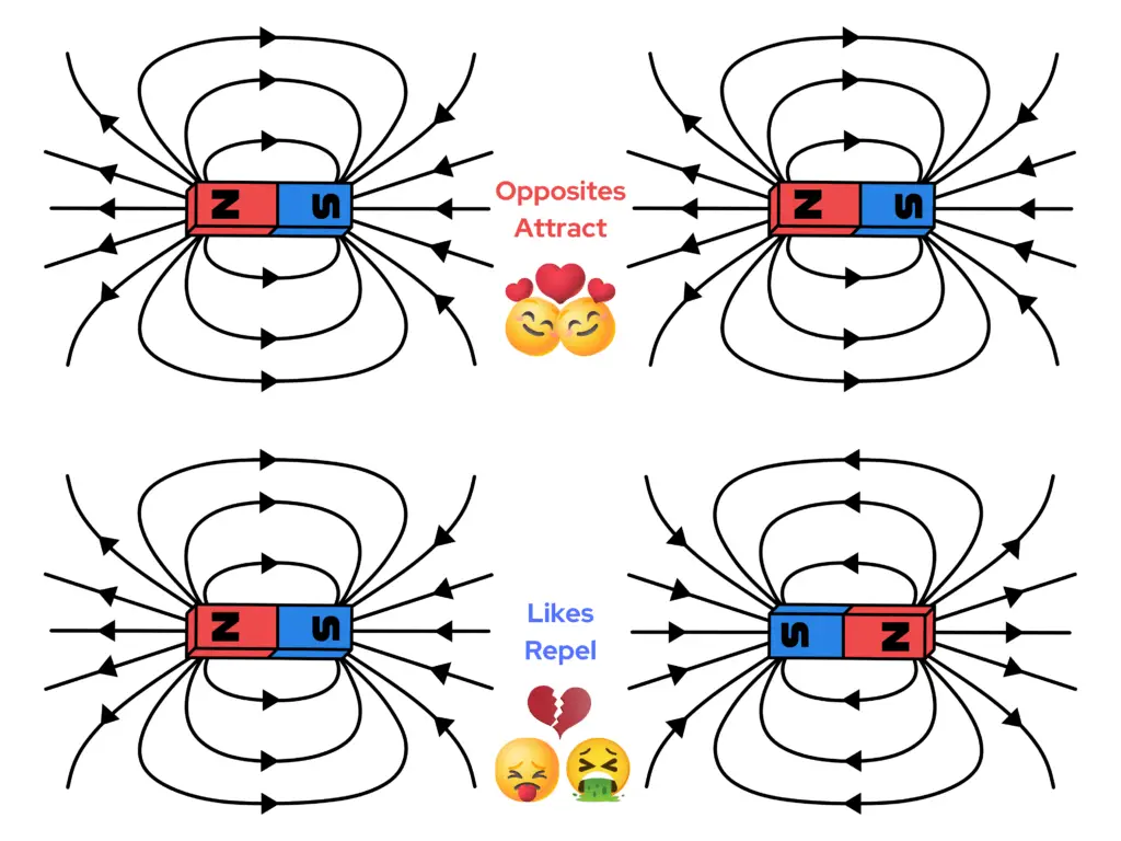
An observation of permanent magnets are that their magnetic poles attract if they are opposite and repel if they are the same, meaning if two bar magnets are facing each other in the following scenarios, the following characteristics of magnets occur:
- North-to-South: The magnetic poles attract each other.
- South-to-North: The magnetic poles attract each other.
- North-to-North: The magnetic poles repel each other.
- South-to-South: The magnetic poles repel each other.

A common permanent magnet is a bar magnet, which are able to attract or move other objects. We can think of a couple scenarios of a bar magnet moving objects:
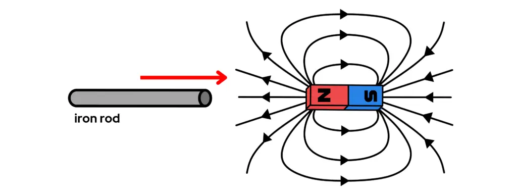
- A Bar Magnet Moving a Piston: We can imagine a rod of iron axially inline with a bar magnet. The job of the bar magnet is to pull the iron rod, as a piston. When the bar magnet comes close to the iron rod, the iron rod gets pulled to the magnet, or the magnet attracts the iron rod via its magnetic field.
- Issue with Bar Magnet Piston: The problem with this scenario is that, although the magnet attracts the piston to move it, there’s no way to turn the magnet “off” to easily release the rod. The rod would have to be manually removed from the magnet.
- A Bar Magnet Moving Another Bar Magnet: Imagine now, that we a bar magnet, we’ll call it magnet A, and another bar magnet, magnet B, axially inline with each other. When magnet A comes close to magnet B, a few couple scenarios occur, depending on the orientation of the magnetic poles of magnets A and B. They’ll either attract or repel each other.
- Issue with Two Bar Magnets: If opposite magnetic poles are facing each other, the two bar magnets will attract each other, again having the same issue as the magnet moving a piston and having to physically remove them from each other. If like magnetic poles are facing each other, the two bar magnets repel each other, meaning they’ll never touch each other.
A Straight Wire
Let’s say that we have a straight piece of copper wire. A length of copper wire on its own, doesn’t do much, but when a current is driven through the copper wire, an observation may be made with the help of a compass. Let’s review two states of the copper wire; with and without a current going through it:
- No Current Through Copper Wire: If we were to place a length of wire on a workbench, not connected to a power source, then place a compass next to it, we wouldn’t observe much going on. The wire is just laying there on the surface, the electrons within it are moving about randomly, not really going anywhere or any particular direction. The compass is also just sitting there on the workbench, pointing in the direction of the Earth’s magnetic field.
- Current Through Copper Wire: If we were to place a power source’s terminals across the copper wire and turn it on, a current would begin to go through the copper wire. When current passes through the copper wire, a magnetic field begins to develop quickly around the wire, as observed in the image below. This developed magnetic field around the wire manipulates the compass needle to then turn in a particular direction, following the magnetic field lines developed around the wire.
If we observe the image below, and imagine that a current was going through the wire, we can see how the magnetic field lines manipulate the compasses placed all around the wire when current is actively going through it. The magnetic field lines wrap around the wire in a concentric pattern when current goes through the wire (remember the curled right hand rule).
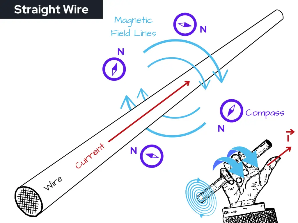
A current carrying straight wire provides a magnetic field, which can be easily controlled, however, the magnetic field around a straight piece of wire is quite weak. To make the magnetic field stronger and more effective, we could wrap the wire into a coil.
A Coil of Wire
Now, let’s say we take a length of copper wire and wrap it around into a coiled shape. We could do this by taking a rigid tubular or solid round bar shaped object, such as a nail, screwdriver, or metal rod, and wind the wire around one of those objects in a spiraling manner, making sure that the coils are compacted together.
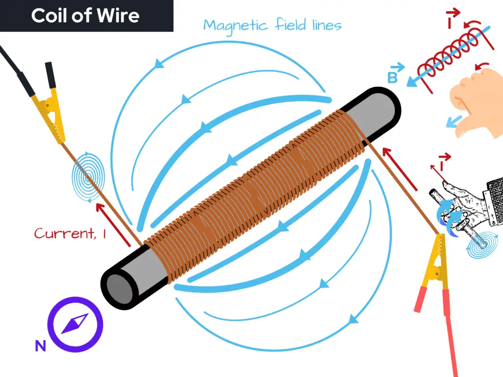
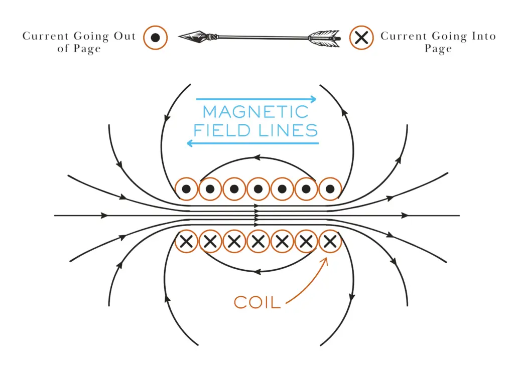
We can see from the image above that when current enters the wire through the red alligator clip (dark red arrow) that a magnetic field builds concentrically around the wire. The wrapped wire around the metal rod, as a whole, creates a larger magnetic field that is centered through the center axis of the rod, or through the center of the coil down the rod’s length, creating an elongated football shaped magnetic field (that’s if the football’s ends were collapsed inward) around the rod as seen in the image below.
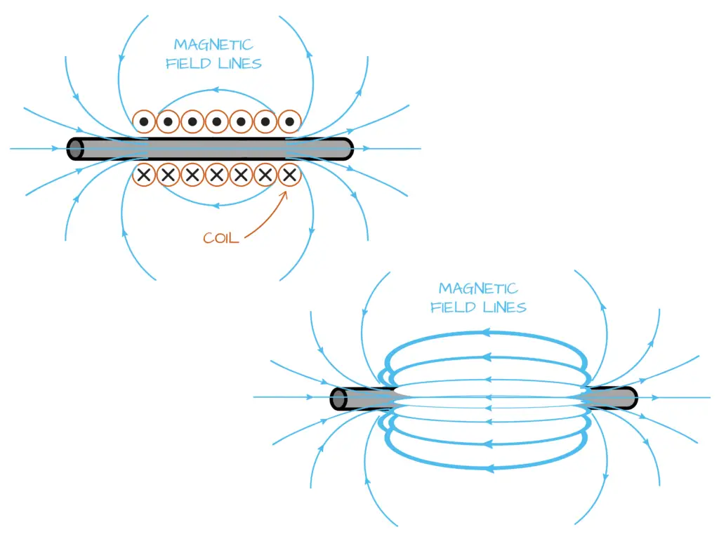
The magnetic field around a coil of wire is much stronger and more useful as a means to control something, like the plunger of a solenoid. We can control this magnetic field and create mechanical motion from electrical current whenever we want, and that’s just what solenoids do. Let’s learn more on how solenoids work.
How do Solenoids Work?
Solenoids are made of coiled wire. To better understand how a solenoid works, let’s further discuss the coil and magnetic field.
A solenoid operates on the principle of electromagnetism, converting electrical energy into mechanical work through the interaction of magnetic fields and electric currents. Here’s a detailed breakdown of how this process occurs:
The Coil and Magnetic Field
- Coil Structure: A solenoid consists of a helical coil of wire, typically made from copper due to its excellent conductivity. The coil is wound tightly to maximize the magnetic field generated when current flows through it. The design allows for a concentrated magnetic field within the coil’s interior.
- Current Flow: When an electric current is introduced into the coil, it generates a magnetic field around the wire, as we discussed earlier. According to Ampère’s law, the strength of this magnetic field is proportional to the amount of current flowing through the coil and the number of turns in the coil. The more turns of wire and the higher the current, the stronger the magnetic field produced.
- Magnetic Field Formation: The magnetic field lines created by the current flow are concentrated within the coil and extend outward. Inside the solenoid, the magnetic field is relatively uniform and strong, while outside, it diminishes rapidly. This characteristic makes solenoids effective for applications requiring a controlled magnetic field.

Interaction with the Plunger
- Plunger Mechanism: Inside the solenoid, there is often a movable metal core known as a plunger or armature. This plunger is typically made of ferromagnetic material, which enhances its magnetic properties.
- Magnetic Attraction: When the current flows through the coil, the magnetic field generated attracts the plunger into the coil. This movement occurs because the magnetic field exerts a force on the plunger, pulling it toward the center of the coil. The plunger’s movement can be linear, allowing it to push or pull other mechanical components in a device.

- Mechanical Work: As the plunger moves, it can perform mechanical work, such as opening or closing a valve, activating a switch, or engaging a locking mechanism, such as on a door. The conversion of electrical energy into mechanical motion is what makes solenoids valuable in various applications, from automotive systems to industrial machinery, or even in controlling wing movement for our OwlBot project, as can be seen here.
Applications of Solenoids
Solenoids can be found in all sorts of every day devices. Some common applications include:
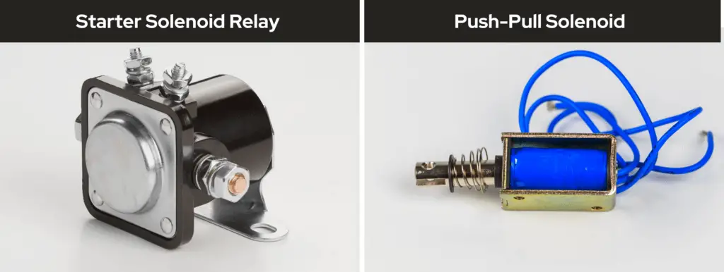
- Automotive systems: Solenoids are used often in automotive systems, such as in starters and locking mechanisms, like door locks and trunk latches.
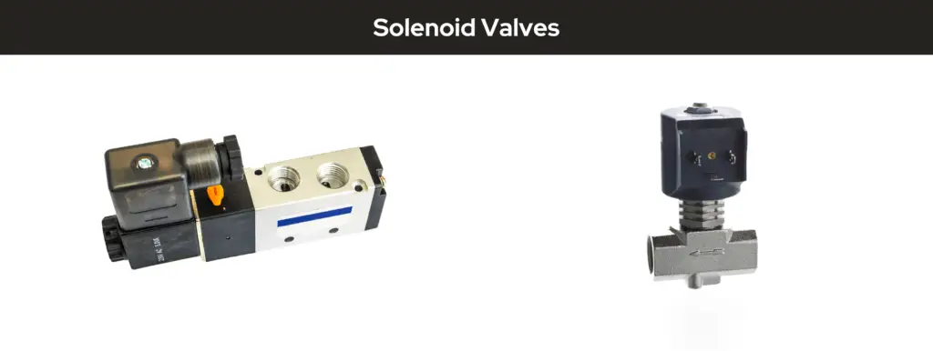
- Industrial machinery: Solenoids are used as actuating valves and for controlling fluid flow. They can be used as valves, such as in hydraulic and pneumatic systems, where they act as actuators to open or close the flow path based on electrical signals.
- Home appliances: Solenoids are used to control water flow, drain valves, and other functions for household appliances, such as washing machines and dishwashers for controlling water flow.
- Robotics applications: Solenoids can be used to provide linear motion to actuate the limbs and joints of robotic systems, such as for the wing movement for our OwlBot project.
- Hobby electronics: Solenoids can be used in a variety of hobby electronics projects, such as creating simple mechanical devices, actuating switches, or providing linear motion for various applications.
Types of Solenoids
Solenoids come in a variety of shapes and sizes, and are used for various types of applications and functionalities. The three main types of solenoids are linear solenoids, rotary solenoids, and latching solenoids.
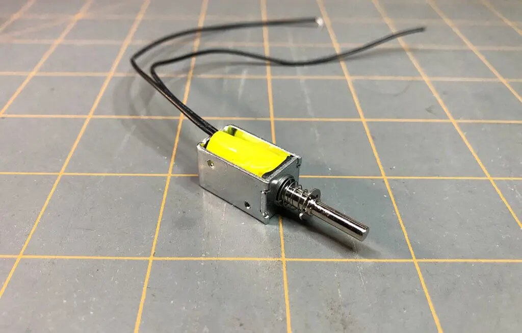
Linear Solenoids
Linear solenoids are the most common type of solenoid. They produce linear motion when an electric current is applied. Here’s how they work and their applications:
- Mechanism: When current flows through the coil, it generates a magnetic field that pulls a plunger (or armature) into the coil. The movement is typically in a straight line, hence the name “linear.”
- Applications: Linear solenoids are widely used in applications such as:
- Locking mechanisms: Engaging and disengaging locks in doors and cabinets.
- Automated valves: Controlling the flow of liquids or gases in various systems.
- Robotics: Providing actuation for robotic arms and other moving parts.
Linear solenoids can also be categorized into different types based on their functionality:
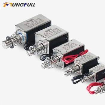
- Simple Linear Solenoids: Simple linear solenoids operate in one direction and require a return spring to reset.
- Reversible Linear Solenoids: Reversible linear solenoids allow for motion in both directions by reversing the current flow.
- Bi-stable or Latching Linear Solenoids: Bi-stable or latching linear solenoids maintain their position without continuous power, useful for applications where power conservation is important.
Rotary Solenoids
Rotary solenoids convert electrical energy into rotational motion. They are designed to rotate a shaft or lever rather than moving linearly.
- Mechanism: When current flows through the coil, it generates a magnetic field that interacts with a rotor or armature, causing it to rotate. The angle of rotation is typically limited to a specific range, often around 90 degrees.
- Applications: Rotary solenoids are used in various applications, including:
- Automated switches: Engaging or disengaging electrical circuits.
- Mechanical devices: Such as locks that require a rotational action to open or close.
- Robotics: Providing rotational movement for joints or tools.
Rotary solenoids are particularly useful in applications where space is limited, and a compact design is required.
Latching Solenoids
Latching solenoids can maintain their position without continuous power. They are designed to switch between two stable states.
- Mechanism: A latching solenoid will typically have two coils. When current is applied to one coil, it pulls the plunger into the coil, switching the solenoid to one state. Applying current to the second coil releases the plunger, switching it back to the original state. This design allows the solenoid to hold its position without needing a constant power supply.
- Applications: Latching solenoids are ideal for applications where power conservation is critical, such as:
- Battery-operated devices: Where minimizing power consumption is essential.
- Control systems: Such as in security systems where a lock needs to remain engaged without continuous power.
- Robotics: For maintaining positions of robotic limbs or components without draining the battery.

Conclusion
The versatility of solenoids is wide ranging and their uses are found in a broad range of applications. The different types of solenoids — linear, rotary, and latching — each serve specific functions and applications. Their ability to convert electrical energy into mechanical motion makes them invaluable in various fields, including automotive, industrial, and hobby electronics.
If you want to see solenoids in action, have a look at our OwlBot project, where we make use of push-pull solenoids to create the action of movement for the wings of the OwlBot. It’s a direct use of solenoids in robotics applications!