The Diverse World of Diodes: Types, Characteristics, and Applications
Introduction to Diodes
A diode is a two-terminal electronic component that allows electric current to flow in only one direction. You can think of a diode as almost like being a check valve for electrical current. Like a check valve for plumbing permits water to flow in one direction, but not the other — the diode permits electrical current to flow in one direction while blocking it in the opposite direction.
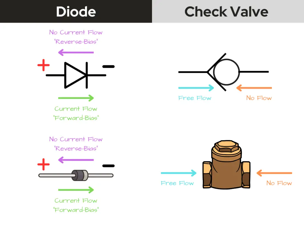
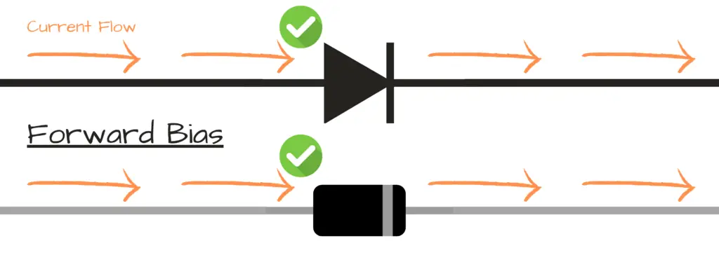
Forward Bias:
- Positive charge of power source to anode (+) of diode terminal — negative charge of power source to cathode (-) of diode terminal.
- At this state, the diode acts as a closed switch — current is allowed to flow through the diode.
Reverse Bias:
- Negative charge of power source to anode (+) of diode terminal — positive charge of power source to cathode (-) of diode terminal.
- At this state, the diode acts as an opened switch — current is not allowed to flow through the diode.

P-N Junction Diode

A diode is considered a P-N junction – meaning that it’s partly-made of a positive-type semiconductor material (P), and is partly-made of a negative-type semiconductor material (N). When oriented in its forward-bias direction, it allows the flow of current through it. When oriented in its reverse-bias direction, it blocks the flow of current.
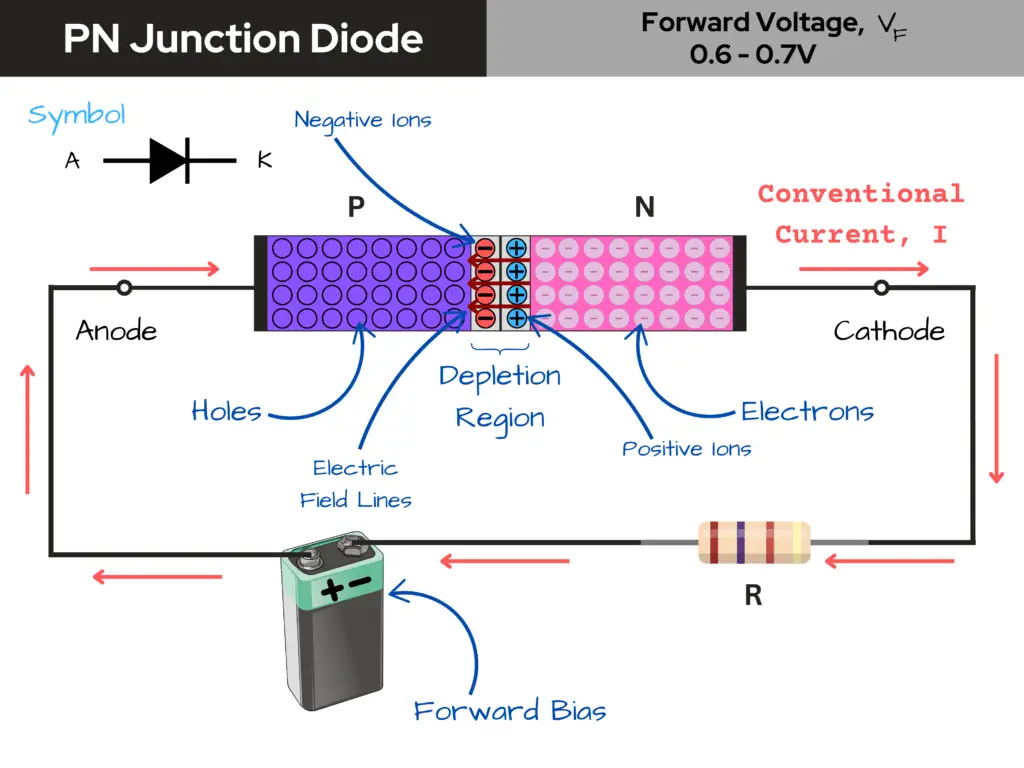
Diodes come in various sizes and shapes, typically with a black cylindrical body and a stripe at one end to indicate the cathode (-) terminal. They are used in a wide range of applications, such as power supplies, signal processing, and voltage regulation.
The key property of a diode is its ability to conduct current in only one direction, making it useful for tasks like converting alternating current (AC) to direct current (DC) in power supplies.
How Diodes Work
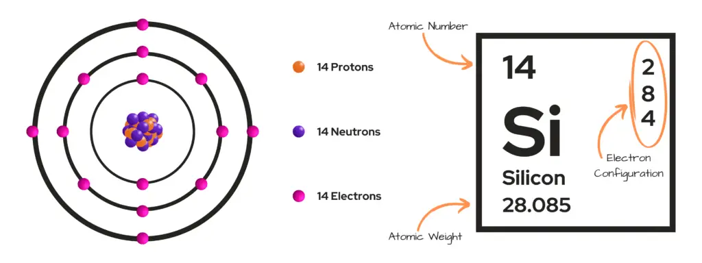
Diodes are made of semiconductor materials, typically silicon or germanium, that are engineered to have a p-n junction. The p-n junction is the key to how diodes function.

When a diode is forward-biased (positive voltage applied to the anode, negative to the cathode), the p-n junction allows current to flow easily through the diode. However, when the diode is reverse-biased (negative voltage applied to the anode, positive to the cathode), the p-n junction acts as an insulator, blocking current flow.

This one-way flow of current is what makes diodes useful for tasks like converting AC to DC power, regulating voltage, and protecting circuits from reverse polarity. The voltage drop across a forward-biased diode is typically around 0.6-0.7V for silicon diodes.
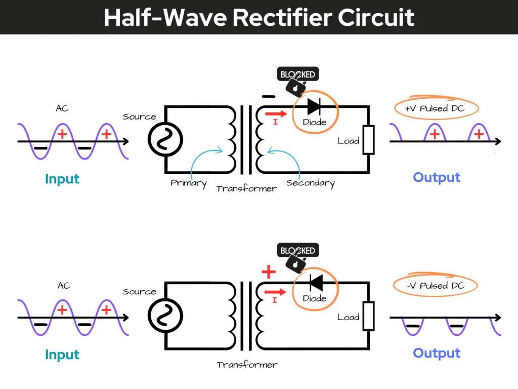
To give you an idea of what a diode can do, let’s take a look at a half-wave rectifier circuit. A half-wave rectifier is the simplest form of rectifier available. It is a device that converts alternating current (AC) to direct current (DC) by allowing only one half-cycle (either the positive or negative half-cycle) of the AC waveform to pass through, while blocking the other half-cycle.
If you want to get a little more detail about p-n junction biases, check out this page at geeksforgeeks.org, where they do a good job to explain forward and reverse-bias of a p-n junction.
Types of Diodes
When it comes to diodes, there are several different types. Let’s quickly review the most common, then later, we’ll go a bit more into detail for each kind:
- Zener Diodes: Used for voltage regulation, as they have a precisely controlled reverse-breakdown voltage.
- Light-Emitting Diodes (LEDs): Emit light when forward-biased. They are used in displays and as indicators.
- Photodiodes: Generate current when exposed to light. They’re used in light sensing applications.
- Schottky Diodes: Have a lower forward voltage drop than standard silicon diodes. They’re useful for power conversion.
- Varactor Diodes: Act as voltage-variable capacitors. These are used in tuning circuits.
Each type of diode has specialized properties and applications based on the semiconductor materials and structure used in its construction. Let’s proceed to review each kind of diode and how they operate.
Zener Diodes
Zener diodes are a special type of diode that allows current to flow in the reverse direction when the voltage across it exceeds a specific value known as the Zener voltage. This property makes them useful for voltage regulation applications, where they can maintain a constant output voltage despite fluctuations in the input. Zener diodes come in a variety of Zener voltage ratings, typically ranging from 2.4V to 200V.
How Zener Diodes Work
- Construction:
- A Zener diode is constructed similarly to a standard diode, with a p-n junction. However, it is specifically designed to operate in the reverse breakdown region.
- Forward Bias:
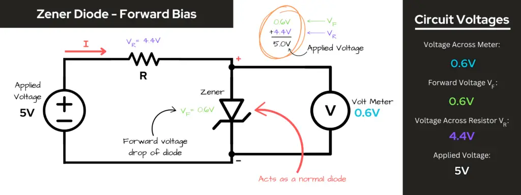
- When a Zener diode is forward-biased (positive voltage applied to the anode), it behaves like a regular diode, allowing current to flow through it with a typical forward voltage drop of about 0.6 to 0.7 volts.
- Looking at the image below, we see that a Zener diode is forward-biased. So, in this case, the Zener diode behaves as a regular diode would, and as current flows through it there’s a typical forward voltage drop (VF) of 0.6V. Using Kirchhoff’s Voltage Law, the sum of the voltage drops across the resistor and diode should equal the source voltage (applied voltage), and it does.
- Reverse Bias:
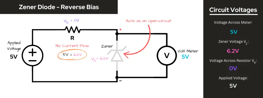
- In reverse-bias, when the voltage applied across the diode is less than the Zener voltage (VZ), then the diode acts as an open-circuit and the voltage read across it equals the applied voltage.
- Looking at the image below, we see a Zener diode in reverse-bias condition in the circuit. The applied voltage is 5V, which is less than the 6.2V Zener voltage (VZ). This means that under this state of the circuit, the threshold voltage has not been met, meaning the Zener diode acts as an open-circuit and no current flows through the circuit. This is why the volt-meter reads 5V across the diode — i.e. the applied voltage must show across the diode, since there’s no voltage drop across the resistor (because of no current flow), according to Kirchhoff’s Voltage Law.
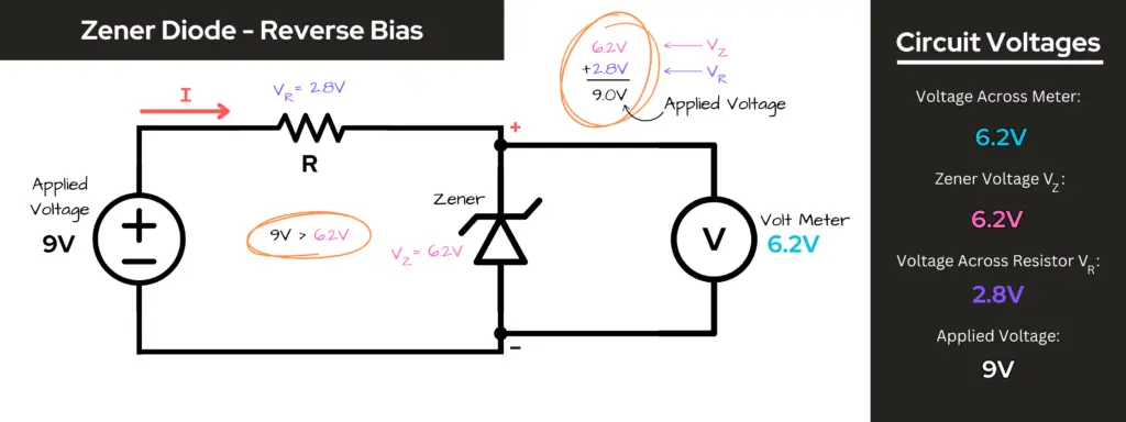
- In reverse bias, when the voltage applied across the diode exceeds the Zener voltage (VZ), the diode enters the breakdown region. Unlike regular diodes that can get damaged in this state, Zener diodes are designed to handle this condition safely. They allow current to flow in the reverse direction, maintaining a nearly constant voltage equal to the Zener voltage.
- Looking at the image below, we see a Zener diode in reverse-bias condition in the circuit. The applied voltage is 9V, which is greater than the 6.2V Zener voltage (VZ). This means that under this state of the circuit, the threshold voltage exceeds the Zener voltage, and current flows through the circuit. The voltage drop across the diode is the Zener voltage (VZ). The voltage drop across the resistor must be 2.8V, because — according to KVL — the sum of the voltage drops across the resistor and the diode must equal the applied voltage of 9V, in this case, which it does.
- This characteristic is what makes Zener diodes effective for voltage regulation. They can keep the voltage across a load constant, even if the input voltage fluctuates or the load current changes.
Applications of Zener Diodes
- Voltage Regulation: Zener diodes are commonly used in power supply circuits to maintain a stable output voltage.
- Overvoltage Protection: They can protect sensitive components by clamping the voltage to a predetermined level.
- Reference Voltage Sources: Zener diodes can provide a stable reference voltage for circuits requiring precision.
Light-Emitting Diodes (LEDs)
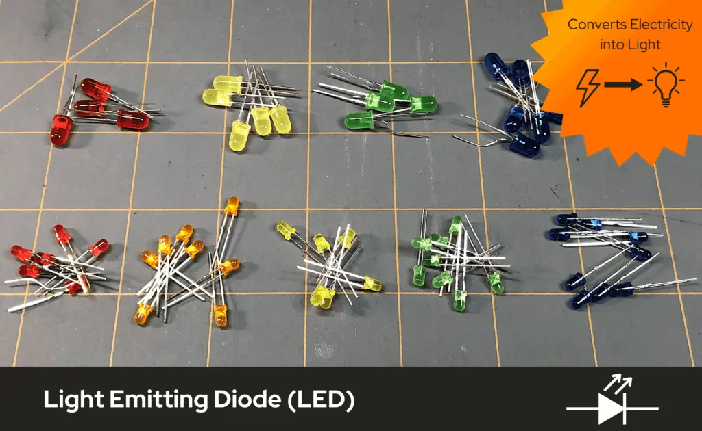
LEDs are a type of diode that can produce light. Just as a diode is a semiconductor, an LED uses semiconductor properties to allow it to illuminate.
An LED, like a diode, is made of two materials that are placed close together. One material is usually a metal, such as aluminum (Al) – the second material is usually a combination or compound of materials, such as gallium arsenide (GaAs).
The makeup of these materials allow them to emit and absorb electrons when an electric potential is applied across the LED’s terminals. When properly biased (forward-bias), electricity is allowed to flow through the LED and the process of emitting and absorbing electrons between the two materials produces light.
If you’re interested in knowing more details about light-emitting diodes, I suggest that you check out our post titled The Bright Side of Technology: A Guide to LEDs.

Photodiodes
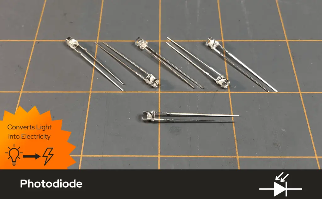
Photodiodes are diodes that generate an electrical current when exposed to light. They are designed to operate in two modes: photovoltaic and photoconductive. They convert optical signals into electrical signals, making them useful for light sensing and detection applications, such as in optical communications, imaging sensors, and light meters.
How Photodiodes Work
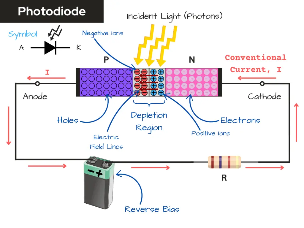
- Construction:
- A photodiode typically consists of a p-n junction, similar to other diodes. However, it is designed to be sensitive to light, often using materials like silicon, germanium, or indium gallium arsenide.
- Working Principle:
- Photon Absorption: When light (photons) hits the photodiode, it can be absorbed by the semiconductor material. If the energy of the incoming photons is sufficient (greater than the bandgap energy of the semiconductor), they can excite electrons from the valence band to the conduction band, creating electron-hole pairs.
- Charge Carrier Movement: The electric field present at the p-n junction (due to the built-in potential) causes the generated electrons to move towards the n-side and the holes to move towards the p-side. This movement of charge carriers creates a flow of current.
- Reverse Bias Operation: Photodiodes are typically operated in reverse bias mode. In this configuration, the p-side is connected to a negative voltage and the n-side to a positive voltage. This enhances the electric field across the junction, allowing for more efficient collection of the generated charge carriers and increasing the sensitivity of the device to light.
- Current Generation: The movement of electrons and holes results in a measurable electrical current. The amount of current generated is proportional to the intensity of the incident light, making photodiodes effective light sensors.
- Operation Modes:
- Photovoltaic Mode: In this mode, the photodiode generates a voltage when exposed to light. This is similar to how solar cells function. When light photons hit the semiconductor material, they can generate electron-hole pairs. If the photodiode is connected to a load, this generated current can be harnessed as electrical power.
- Photoconductive Mode: In this mode, the photodiode is reverse-biased. When light strikes the diode, it generates electron-hole pairs, which increase the current flow through the diode. This mode is typically used for higher-speed applications, as the reverse bias allows for faster response times.
- Light Detection:
- Photodiodes are sensitive to various wavelengths of light, making them suitable for applications requiring light detection. The amount of current generated is proportional to the intensity of the incident light, allowing the photodiode to act as a light sensor.

Applications of Photodiodes
- Optical Communications: Photodiodes are used in fiber optic systems to convert light signals into electrical signals, enabling high-speed data transmission.
- Imaging Sensors: They are used in cameras and imaging devices to detect light and convert it into images.
- Light Meters: Photodiodes can measure light intensity in applications such as photography and environmental monitoring.
- Safety Systems: They are used in smoke detectors and other safety systems to detect changes in light levels.
Schottky Diodes
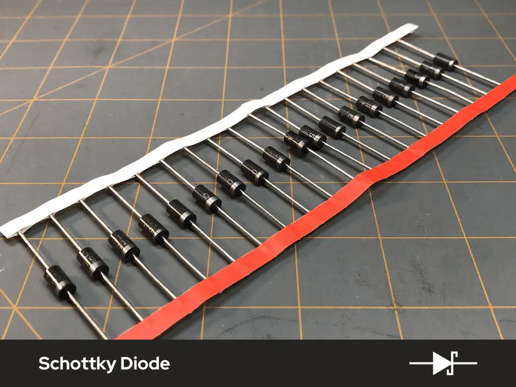
Schottky diodes are a type of diode that have a lower forward voltage drop compared to standard silicon diodes. Unlike regular p-n junction diodes, Schottky diodes are formed by the junction of a metal and a semiconductor, rather than two doped semiconductor materials. This construction allows for their lower voltage drop which makes them more efficient for power conversion and rectification applications, such as in power supplies and switching circuits.
How Schottky Diodes Work
- Construction:
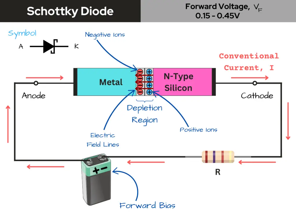
- A Schottky diode consists of a metal layer (typically made of materials like gold, platinum, or aluminum) and a semiconductor layer (usually n-type silicon). The metal-semiconductor junction creates a barrier that allows current to flow in one direction (forward direction) while blocking it in the reverse direction.
- Forward Bias Operation:
- When a Schottky diode is forward-biased (the anode is more positive than the cathode), electrons from the n-type semiconductor move toward the metal layer, allowing current to flow. The forward voltage drop in Schottky diodes is typically between 0.15 to 0.45 volts, which is lower than that of standard silicon diodes (around 0.6 to 0.7 volts).
- Reverse Bias Operation:
- In reverse bias, the Schottky diode blocks current flow, preventing it from passing in the reverse direction. However, Schottky diodes have a lower reverse breakdown voltage compared to other diode types, so they are not suitable for high-voltage applications.
- Fast Switching:
- Due to the absence of a charge storage layer (as seen in p-n junction diodes), Schottky diodes can switch on and off much faster. This makes them ideal for high-frequency applications.
Applications of Schottky Diodes
- Power Rectifiers: Schottky diodes are commonly used in power supply circuits, particularly in switching power supplies, due to their low forward voltage drop and efficiency.
- Radio Frequency (RF) Applications: Their fast switching speed makes them suitable for RF applications and high-speed digital circuits.
- Clamping Circuits: Schottky diodes can be used in clamping circuits to prevent voltage spikes from damaging sensitive components.
- Solar Cell Applications: They help improve the efficiency of solar panels by minimizing power loss during rectification.
Other Names for Schottky Diodes
- Schottky Barrier Diode
- Surface Barrier Diode
- Hot Electron Diode
- Hot Carrier Diode
- Majority Carrier Diode

Varactor Diodes
Varactor diodes, also known as varicap diodes, are a type of semiconductor diode that functions as a voltage-controlled capacitor. Varactor diodes exploit the property of the p-n junction to vary their capacitance based on the reverse voltage applied across them. Their capacitance changes with the applied reverse-bias voltage, making them useful for tuning and frequency control applications, such as in radio and television receivers.
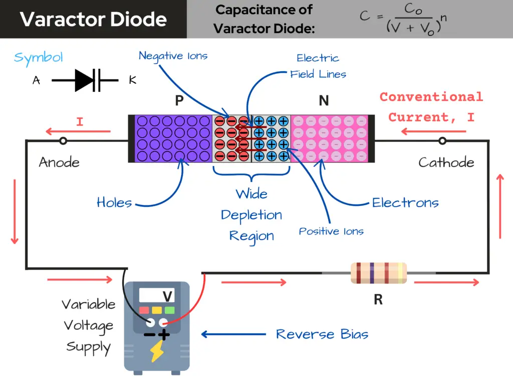
How Varactor Diodes Work
- Construction:
- A varactor diode is constructed like a regular p-n junction diode, but it is specifically designed to take advantage of the capacitance change that occurs when a reverse voltage is applied. The diode is typically made from silicon or gallium arsenide.
- Capacitance Variation:
- When a reverse voltage is applied to the varactor diode, the depletion region (the area near the p-n junction where charge carriers are depleted) widens. As the depletion region increases, the effective capacitance of the diode decreases.
- Conversely, when the reverse voltage is reduced, the depletion region narrows, and the capacitance increases. This relationship between the reverse voltage and capacitance allows the varactor diode to act as a variable capacitor.
- Capacitance Formula:
- The capacitance C of a varactor diode can be approximated by the formula: C = C0/(V+V0)n
- where C0 is the capacitance at zero bias, V is the reverse voltage, V0 is a constant related to the diode’s characteristics, and n is a constant that depends on the doping levels of the diode.
Applications of Varactor Diodes
- Tuning Circuits: Varactor diodes are commonly used in radio frequency (RF) circuits to tune oscillators and filters by varying the capacitance with a control voltage.
- Frequency Modulation: They are used in FM transmitters and receivers to modulate the frequency of the signal based on the applied voltage.
- Phase-Locked Loops (PLLs): Varactor diodes are integral components in PLL circuits, where they help stabilize frequencies.
- Automatic Frequency Control (AFC): They assist in maintaining the correct frequency in communication systems.
Other Names for Varactor Diodes
- Varicap
- Tuning Diode
- Variable Capacitance Diode

Tunnel Diode
A tunnel diode, also known as an Esaki diode, is a type of semiconductor diode that exhibits negative resistance due to the quantum mechanical effect called tunneling. It features a heavily doped p-n junction that is extremely narrow, allowing electrons to “tunnel” through the energy barrier rather than climbing over it.
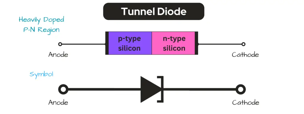
Tunnel diodes are used in applications that require high-speed operation and low voltage. They are particularly effective in oscillators, amplifiers, and switching circuits due to their ability to switch states rapidly. Their unique characteristics make them suitable for use in high-frequency electronics and microwave applications, where traditional diodes may not perform as effectively.
Avalanche Diode
An avalanche diode is a type of semiconductor diode specifically designed to operate in the reverse breakdown region. It is engineered to experience avalanche breakdown at a predetermined reverse bias voltage, allowing it to conduct current safely without damage.
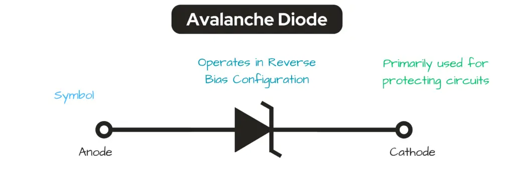
Avalanche diodes are primarily used for surge protection and voltage regulation in electronic circuits. They act as protective devices, safeguarding electrical systems from excess voltages by clamping the voltage to a safe level. This makes them ideal for applications in power supplies, transient voltage suppression, and overvoltage protection systems, where they help prevent damage from voltage spikes.
Difference Between Zener Breakdown and Avalanche Breakdown
Both Zener breakdown and avalanche breakdown are mechanisms that occur in semiconductor diodes when they are reverse-biased, leading to a significant increase in current. However, they differ in their underlying mechanisms and the conditions under which they occur.
| Zener Breakdown | Avalanche Breakdown | |
| Mechanism: | Zener breakdown occurs due to a high electric field in the depletion region of a diode. When the reverse voltage is sufficiently high, it creates a strong electric field that can pull electrons from their valence band, allowing them to contribute to conduction. | Avalanche breakdown occurs due to the collision of free electrons with atoms in the semiconductor. As the reverse voltage increases, the kinetic energy of the electrons also increases, leading to collisions that generate additional electron-hole pairs. This process creates a chain reaction, resulting in a large increase in current. |
| Voltage Range: | This phenomenon typically occurs at lower reverse voltages, usually below 5-6 volts. It is commonly observed in Zener diodes, which are designed to operate in this breakdown region. | Avalanche breakdown typically occurs at higher reverse voltages, generally above 6 volts. It is observed in both regular diodes and Zener diodes when the reverse voltage exceeds the Zener breakdown voltage. |
| Characteristics: | Zener breakdown is characterized by a relatively sharp increase in current with a small increase in voltage. It is a controlled breakdown, allowing Zener diodes to maintain a stable output voltage. | The current increases rapidly with an increase in voltage, leading to a more significant and less controlled breakdown compared to Zener breakdown. This can potentially damage the diode if not managed properly. |
Common Types of Diode Circuits
Flyback Diode (Freewheeling Diode)
A flyback diode is a diode connected across an inductive load, such as a relay coil or a motor, to protect the circuit from voltage spikes that occur when the current flowing through the inductor is suddenly interrupted.
This phenomenon is known as flyback or back EMF (Electromotive Force). When the current is cut off, the collapsing magnetic field around the inductor generates a high voltage spike in the opposite direction, which can damage other components in the circuit.
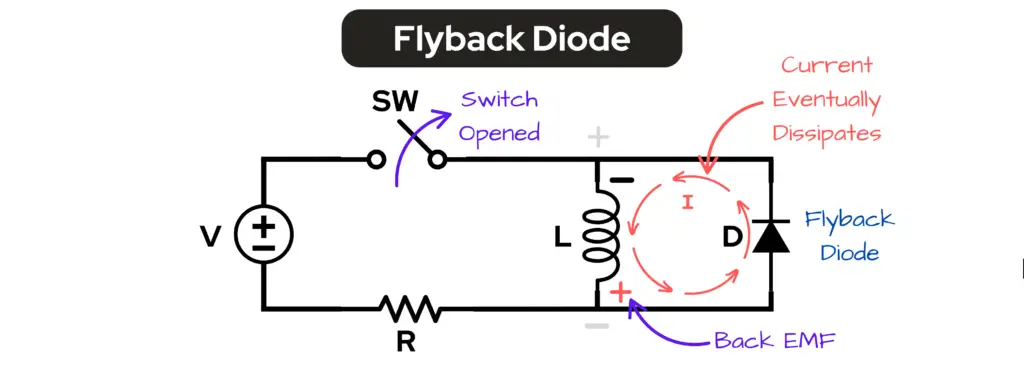
How Flyback Diodes Work
- Inductive Load Behavior: When current flows through an inductor, it stores energy in the magnetic field. If the current is suddenly interrupted (e.g., by opening a switch), the energy stored in the magnetic field must go somewhere. This results in a high voltage spike across the inductor.
- Diode Action: The flyback diode is oriented in reverse bias relative to the power supply during normal operation. When the switch is opened and the current is interrupted, the diode becomes forward-biased due to the induced voltage from the collapsing magnetic field. This allows the current to flow through the diode, effectively providing a path for the current and dissipating the energy safely.
- Voltage Spike Suppression: By providing a path for the current, the flyback diode prevents the high voltage spike from reaching sensitive components, thus protecting them from damage.
Diode Clipper Circuit
A diode clipper circuit is an electronic circuit that uses diodes to “clip” or cut off portions of an input signal, resulting in a modified output waveform. These circuits are commonly used in various applications to protect sensitive components from voltage spikes, shape waveforms, or limit signal amplitudes.
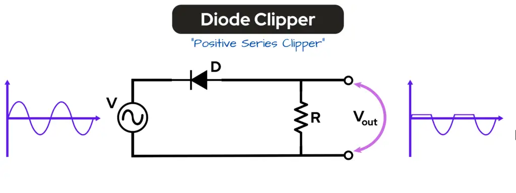
How Diode Clippers Work
Diode clippers operate based on the non-linear characteristics of diodes. When a diode is forward-biased, it allows current to flow, while in reverse bias, it blocks current. This property is exploited to control which parts of the input signal are allowed to pass through to the output.
- Clipping Action: The diode clips the input signal at a certain voltage level. For example, if a diode is oriented to conduct during the positive half-cycle of an AC signal, it will allow that portion to pass while clipping off the negative half-cycle. This results in an output waveform that resembles a flattened version of the input signal.
- Types of Clippers:
- Positive Clipper: Clips the positive portion of the waveform above a certain threshold voltage.
- Negative Clipper: Clips the negative portion of the waveform below a certain threshold voltage.
- Combination Clipper: Clips both the positive and negative portions of the waveform.
Applications of Diode Clippers
- Signal Shaping: Diode clippers are used to shape waveforms in signal processing applications, ensuring that signals remain within desired voltage levels.
- Voltage Protection: They can protect sensitive electronic components from voltage spikes by limiting the maximum voltage that can reach the component.
- Rectification: In rectifier circuits, diode clippers can help maintain a predefined voltage level, ensuring that the output does not exceed certain limits.
Diode Clamping Circuit
A diode clamping circuit is an electronic circuit designed to shift the voltage level of an input signal, either upward or downward, by adding or subtracting a DC voltage. This is achieved using diodes, capacitors, and sometimes resistors, allowing the circuit to maintain the shape of the waveform while adjusting its DC level.
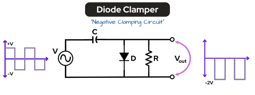
How Diode Clamping Circuits Work
- Basic Components: A typical clamping circuit consists of a diode, a capacitor, and a resistor. The diode controls the direction of current flow, while the capacitor stores charge and helps in shifting the voltage level.
- Voltage Shifting: The primary function of a clamping circuit is to add or subtract a specific DC voltage to the input signal. For example, if a positive DC voltage is added, the output waveform will be shifted upward. Conversely, if a negative DC voltage is subtracted, the output will be shifted downward.
- Operation: When the input signal is applied, the diode conducts during certain portions of the waveform, allowing the capacitor to charge to the peak voltage of the input signal minus the forward voltage drop of the diode. When the input signal goes below this level, the diode becomes reverse-biased, and the capacitor maintains the voltage level, effectively clamping the output.
Types of Clamping Circuits
- Positive Clamping Circuit: This circuit shifts the entire waveform upward. It typically uses a diode that conducts during the positive half-cycle of the input signal, allowing the capacitor to charge and maintain a higher voltage level.
- Negative Clamping Circuit: This circuit shifts the waveform downward. The diode conducts during the negative half-cycle, allowing the capacitor to charge negatively, thus clamping the output to a lower voltage level.
Applications of Diode Clamping Circuits
- Signal Conditioning: Clamping circuits are used in signal processing to ensure that signals remain within specific voltage ranges, which is crucial for interfacing with other electronic components.
- Protection of Circuits: They can protect sensitive components from voltage spikes by clamping the voltage to safe levels, preventing damage from overvoltage conditions.
- Waveform Shaping: Clamping circuits are also employed in waveform shaping applications, where it is necessary to adjust the DC level of a signal without altering its overall shape.
Conclusion
Diodes play a crucial role in electronic circuits by controlling the direction of current flow and protecting sensitive components from voltage transients. Their versatility allows them to be used in various applications, from simple rectifiers to complex clamping and protection of circuits.
Understanding how diodes function and their applications is fundamental for anyone working in electronics, as they are integral to the reliability and efficiency of electronic systems.
If you have any questions or comments, leave them down in the comments section below, and if you haven’t done so already, sign up for our newsletter to stay informed of new content and projects that happen here, at Motbots!
Remember to keep at it and stay motivated.
