Understanding Circuit Symbols and Schematics: The Road Maps of Electronics
Introduction
The following is Part 2, of a planned 12 part super series on the topic of components. We started with what components are – now we’re moving onto the topic of circuit component symbols and schematics. Later, we’ll progressively work through more topics and ideas of components, further advancing these ideas into a robot project to really get you to understand how they work together to create something awesome and useful.
The following is how this 12 Part Super Series on Components will progress, in order:
- What Is a Component?
- Understanding Circuit Symbols and Schematics (⬅️ YOU ARE HERE)
- How Components Work Together in Real Circuits
- Putting Components to Work
- Introducing Microcontrollers
- Smart Circuits Meet AI
- Teaching Robots to Move
- How Sensors, Data, and AI Create Perception
- Human–Robot Interaction
- Decision Making and Autonomy in Robots
- Robotic Navigation
- Distributed Robotics, Swarms, and Multi-Agent Intelligence
Let’s get started with Part 2: Understanding Circuit Symbols and Schematics
You’ve Already Met the Components
So, you’ve met the components — the resistors, capacitors, inductors, diodes, LEDs, and transistors that make your gadgets go bleep, bloop and flash a light show. But then someone hands you a circuit schematic, and suddenly you’re staring at a page filled with lines, zigzags, arrows, and mysterious shapes. It looks like something a treasure hunter would find on an ancient scroll – “What is this?”, you ask as a deep sense of panic hits your chest.
Don’t panic — you’re not decoding alien hieroglyphs. You’re just learning the symbology of electronics, and once you learn it, you’ll see that schematics are really just “maps” showing where the electrons flow and how each component plays its part along the highways of conductors within a circuit.
So, to start our electronics road trip adventure, let’s find out what exactly a schematic is.

🗺️ What Exactly Is a Schematic?
If you’re familiar with the construction trades or have ever helped design a house you wanted to build, you’ve probably seen a blueprint. A blueprint shows the details of a house’s floor plan — it may even show electrical and plumbing layouts throughout the house design. The blueprint shows how the house will be built and gives the instructions to the builders how it should be made.
A schematic diagram is the blueprint of an electronic circuit. It’s how engineers, hobbyists, and even your microwave’s designer communicate how components are connected — without needing a physical board or wires.
You could think of a schematic diagram of an electronic circuit as a map of a city for electrons:
- The lines are the roads (wires) that electricity travels along.
- The symbols are the aids or obstacles (components) that do something useful — resistors limit flow, capacitors store energy, transistors switch or amplify signals.
- The arrows and labels are your street signs, telling you which way the current flows.
If you’d like to really drive home how some of the components work within a circuit, check out our racetrack analogy of circuits on our page titled What is a Circuit?, where we kind of keep with this theme or idea of a road and the components compared to being different items on that road.
Once you’ve done that, we can move on to see what the most common circuit symbols are, and get ourselves familiar with them.
🧩 The Most Common Circuit Symbols (and What They’re Trying to Tell You)
Circuit symbols are like road signs for electronics. They specify what it is that is trying to be portrayed on the circuit highway — how it works, what it does, where electricity is flowing, etc. Let’s decode the ones you’ll see most often when you start reading schematics. We’ll keep with the road theme here.
Resistor – The Zigzag Line
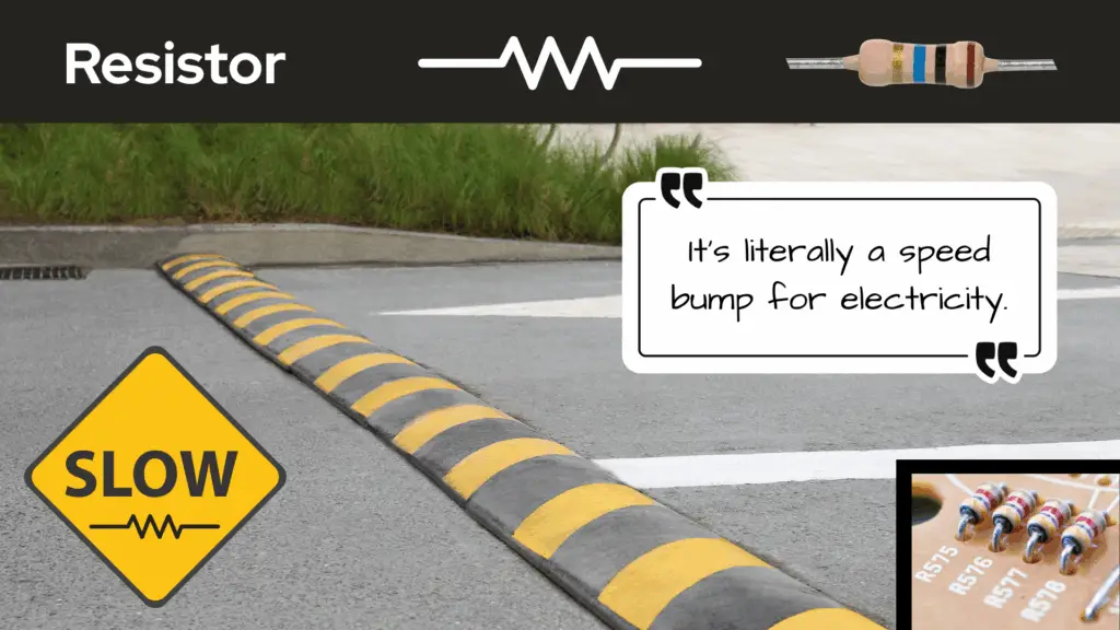
A resistor is easy to recognize in any schematic — they always look like a zigzag line. It’s like someone sneezed as they were attempting to draw a straight line.
Also know that a resistor can sometimes be drawn as a rectangular box. You’ll see an example of this on the schematic for a blinking LED circuit we’ll do in the next part of this series, How Components Work Together in Real Circuits. But most of the time the resistor is drawn like some needed a handkerchief.
This symbol means, “Slow down, current!” In schematics, resistors are often labeled with an “R” followed by a number (R1, R2, etc.) and sometimes a value — like “10kΩ” (that’s 10,000 ohms).
The resistor is measured in units of ohms [Ω] (Ω, is the uppercase Greek letter for omega), named after the German physicist Georg Simon Ohm.

It’s literally a speed bump for electricity — and every circuit needs a few. You can think of the symbol of the resistor as meaning that the current will slow down at that location of the circuit, and that the value of the resistor is how many speed bumps there are for current. The higher the value of the resistor, the more speed bumps there are for current.
“So, you’re comparing 10,000kΩ, as an analogy of having 10,000 speed bumps?!”
Well, yes, sort of. It’s just an analogy.
“That’s a lot of speed bumps!”
Resistors oppose the flow of current, so you can imagine that if you had to drive through several speed bumps, they’d be impeding your ability to travel more freely through that section of road you’re “flowing” through.
Just as having a lot of speed bumps would impede your ability of travel in your car on the road, having a larger value of resistance also impedes the ability of current to flow through a conductor, in a sense.

Capacitor – The Parallel Lines (or One Straight, One Curved)
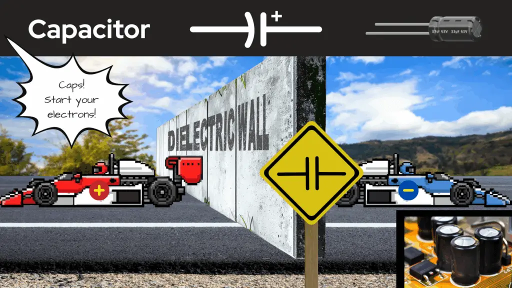
It was difficult to come up with a road themed analogy for the capacitor, but on our page What is a Circuit?, an analogy was made for a new racetrack game that our race car drivers made. The race included a concrete wall on the track, and that concrete wall was used as the analogy for a capacitor. I highly suggest you go check that analogy out to hopefully better understand what a capacitor does.
Capacitors are drawn to look like two plates facing each other — which makes sense, because that’s basically what they are. In schematics, capacitors are often labeled with a “C” followed by a number (C1, C2, etc.).
The capacitor is measured in units of farads (F) — named after English chemist and physicist Michael Faraday — but more commonly measured in much smaller units like microfarads (µF), nanofarads (nF), and picofarads (pF).

If you see a tiny “+” nearby, that means it’s a polarized capacitor (like an electrolytic capacitor), and yes, it does matter which way you connect it. Get it backwards, and you might turn your project into a smoke machine. (We’ve all done it once.)
Capacitors oppose any sudden changes in voltage potential across them. What this means is the voltage across a capacitor, for the most part stays constant. This is what is meant by capacitors smoothing out voltage fluctuations.
Inductor – The Loopy Coil
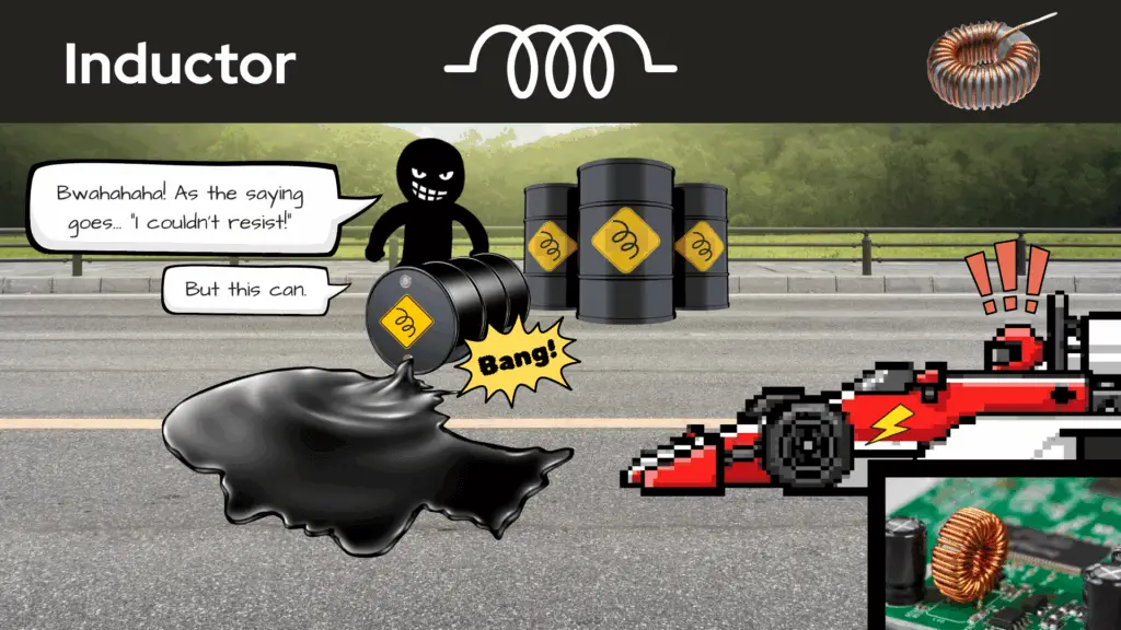
It was difficult to come up with an analogy for the inductor as well, that would keep with the road theme we’ve got going, but I think a fairly good one was made on our page, What is a Circuit? There, the analogy of an inductor as being a large oil slick on a racetrack was made. If you’re interested in hearing that analogy (and like race cars), go check it out!
Inductors are drawn as loops or squiggly lines — because they’re basically coils of wire.
In schematics, inductors are often labeled with an “L” followed by a number (L1, L2, etc.). The designation of the letter “L” is done in honor of Heinrich Friedrich Emil Lenz, who made significant contributions to electromagnetism — particularly Lenz’s Law.
The inductor is measured in units of henry [L], named after the 19th century American scientist Joseph Henry. (I know. All this labeling and units of measure is confusing, but you’ll get it.)
Inductors resist any sudden changes in current through them. Whenever you see one, think: “Magnetic field. Energy storage. Possible hum noise in speakers.” They’re less common in beginner projects but totally worth recognizing.
Diode – The One-Way Arrow
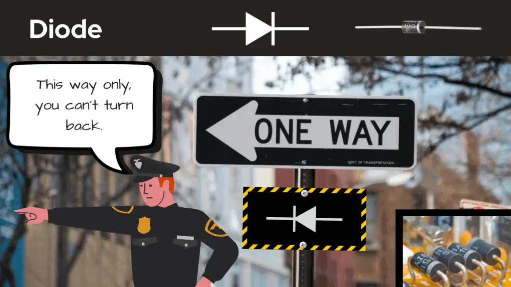
A diode is like a one-way street sign for electrons in a circuit. It says, “This way only, you can’t turn back.” In schematics, diodes are often labeled with a “D” followed by a number (D1, D2, etc.).
A diode drawn on a schematic looks like an arrow pointing at a wall — current can go in the direction of the arrow, but cannot come back through the wall. If it’s an LED, it’ll have little arrows coming out of it like it’s shouting, “Look at me! I’m glowing!”
Diodes are measured in terms of their electrical characteristics – like voltage (V), current (I), and power (W). There’s also different types of diodes, like Zener diodes, light emitting diodes (LEDs), Schottky diodes, and others.
Transistor – The Circle With Lines and an Arrow
We can think of a transistor as like being a signal light at a busy intersection, elegantly guiding traffic. Transistors direct electrons to their destinations throughout a circuit — whether to amplify or switch electrical signals and power.
Transistors are drawn in a way that looks complicated at first — but once you know the parts (collector, base, emitter), it’s not so bad. Just remember:
- NPN: Not Pointing iN (arrow points out or away from symbol)
- PNP: Pointing iN Proudly (arrow points in or toward symbol)
Transistors act as amplifiers, because they can increase the strength of week signals coming into a circuit. They also act as switches, turning electrical signals on and off — both characteristics being crucial in audio and communications devices, as well as in digital circuits and computing.
This signal control of circuits is the base of what is allowed to flow on the electrical roadway. It only let’s electrons through if it says so.
Ground – The Lines That Get Gradually Smaller
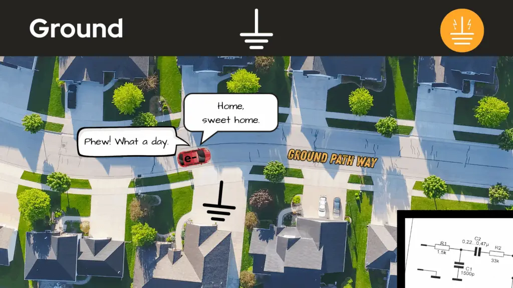
The ground symbol is usually drawn like a line terminating perpendicularly into three parallel horizontal lines stacked onto each other (with some spacing) that gradually decrease in length.
This symbol means, “This point is connected to zero volts or to the zero reference.”
Keeping with using the road theme, we can think of ground as the road back home. Electrons leave home for work for the day — doing the rat-race throughout the circuit — then, come back home for the night.
In other words, ground is the return path for the circuit’s electricity — where all the electrons come home for the night. If you connect things wrong here, nothing works… or everything works once (before it doesn’t).
Battery – The Tall and Short Line Pairs

This one’s easy — the battery symbol is drawn like a stack of cells. The longer line is the positive terminal, the shorter one is negative.
Keeping with the road theme, we can think of the battery as the engine for the electrons to move throughout the circuit. I know, I know — cars have a battery for ignition purposes and to power their electronics, but let’s just think of the battery of a circuit as being the circuit’s engine, okay? Work with me here.
So, if we’re talking about engines, the smaller the engine, the less power there is to move along the road — the greater the engine, the more power there is to move along the road.
Similarly, for a battery, the greater the voltage it has, the more potential it has to push the electrons about the circuit — the lesser the voltage, the less potential it has to push electrons about the circuit.
Whenever you see multiple cells, you’re looking at more voltage — more power for your project (and more ways to accidentally fry something fun).
🔌 Wires and Connections: The Circuit’s Highways
Lines on a schematic represent wires or traces (the copper paths on a circuit board). We can think of them as the circuit’s highways, roads, streets, and routes for electrons.
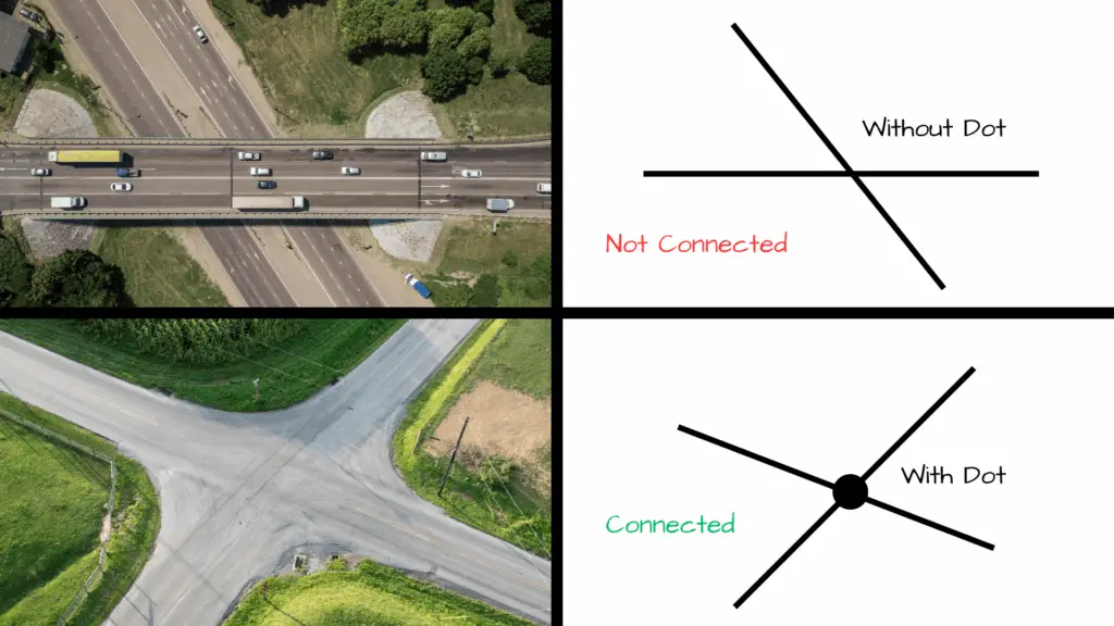
When looking at a schematic, you may see lines intersecting each other. Sometimes these lines have a dot where they intersect, sometimes they don’t. Seeing these intersecting lines — some with dots, some without — may seem confusing at first, but don’t let this little detail fool you, it’s actually quite simple to understand.
- When two lines cross without a dot, they don’t connect — they’re just passing each other.
- When there’s a dot at the crossing, it’s a connection — electricity can flow between those lines.
Think of it like traffic intersections. No dot? Different roads. Dot? Intersection. Beep beep.
💬 How to Read a Schematic Without Losing Your Mind
If you’ve never read a schematic, it can feel daunting and intimidating to look at, but as with everything new that is tried, you just have to dig deep and do it. It’s like I always say, “There ain’t nothing to it, but to do it!”
There ain’t nothing to it, but to do it!
The only advice I can give is to just allow yourself to study a schematic — even if you have no clue what you’re looking at — and get the feel of how the circuit flows.
When you read one:
- Find the power source — where the electricity begins. If we’re following convention, this would be the positive (+) terminal of the power source (battery) — that’s our starting point.
- Trace the path — follow the lines through each component, starting at our starting point.
- Look at labels — components are numbered (R1, C2, D3, etc.) to make them easy to reference on the parts list.
- Notice the flow direction — arrows and polarity signs show how current moves. Diodes say, “This way only.” Resistors say, “Slow down!” Capacitors say, “When charged up, I resist any sudden changes in voltage.” Inductors say, “I resist any sudden changes in current.” Transistors say, “When current comes to the gate (G), I allow a path for more current to go from drain (D) to source (S).”
Just like with anything in life, to get good at it you have to keep doing it. With practice, you’ll start to “see” the circuit doing its thing in your mind.
Pretend that the schematic is a movie. We’ll call this movie, The Life of Electrons: Going Back to Zero Reference. You have to use a bit of your imagination to see how the life of electrons are played out in Circuit City (no relation to the retail company). This mental movie is where electrons are the main characters and each path they take and component they come up against is a part of their story, until they finally come back home to ground or zero reference.

🧠 Bonus Tip: Learn by Reverse Engineering
Want to learn faster? Grab a simple schematic, like the one from our Chewing Gum Box LED Night Light project, and build it on a breadboard.
As you place each component, look back at the schematic — trace the lines, match the symbols, and see how it all connects.
You’ll quickly realize that schematics aren’t mysterious — they’re logical and consistent. The moment it clicks, you’ll feel like you’ve just unlocked a new superpower.
🚀 Why Schematics Matter
Every engineer, hobbyist, or inventor you’ve ever admired — from Nikola Tesla to the guy who made that homemade hydrogen fuel-cell car out of his garage on YouTube — knew how to maneuver about the landscape of a schematic, and understood the signs it told.
It’s the common ground between idea and reality (no pun intended). You can dream up a device in your head, draw it as a schematic, and then physically build it. It’s quite a wonderful thing that we humans are capable of doing:
- Think of an idea.
- Communicate that idea using pencil and paper (or software).
- Use commonly understood symbols to communicate that idea.
- Build off that idea.
As you can see, schematics matter an awful lot to us creative humans. In a sense, schematics are the blueprint of imagination. They turn “I wonder if…” into “Hey, look what I built!”
🎬 Wrapping It Up: You Can Read the Signs
So, what started out looking like spaghetti art, or a 4 year old’s scribbled drawing, actually makes perfect sense once you know what you’re looking for. It’s like reading a road map of a city — each symbol and line telling you where electrons go throughout the circuit’s highways, byways, and side streets.
Every squiggle, arrow, and zigzag on that page has its place and meaning in the grand scheme of the design of the circuit. It’s almost like reading the pages of a book that tells a story — one of energy, balance, timing, and clever design.
Now, when someone says “Check out this circuit diagram,” you can proudly say, “Oh yeah, I can totally understand this. It’s like reading a map, for electrons.”
What’s Next?
Now that we know component symbols and have a bit more knowledge of how to read and recognize them in schematics, let’s test our skills! In the next part of this series, we’ll learn how the components work together in real circuits. From there, we’ll see them in a real schematic diagram that we’ll use to create a real circuit!

Thank you for joining us on this journey of electronic components, thus far. We hope that you have enjoyed learning about circuit symbols and schematics. Let us know by giving a comment in the comments section below. Share the link to your friends and family. Let them know how much you’ve enjoyed the process of learning about circuit components.