What Exactly Is an Astable Multivibrator? (An Extended Topic for the LED Blinker Circuit)
Introduction
The following content is intended to be a companion to the LED blinker circuit we created from our article titled, “How Components Work Together in Real Circuits.”
The sole purpose of this discussion is to work as an extended topic for that article to help you understand your circuit better, and to help clarify what an astable multivibrator is and how it’s related to the LED blinker circuit.
The following is meant to be thorough, and codified in a way to be understandable to any reader, no matter their background, thought process, or way of learning — at least we hope that it is. There have been several different attempts to express the content for this discussion here in hopes to be accessible for all.
We hope that you find the following to be useful.
The LED Blinker Circuit is an Astable Multivibrator
The LED blinker circuit is an astable multivibrator. What’s that? Well, before we get into your circuit and how it works, we’ll first briefly go over what an astable multivibrator is, go over some of the history of it, then we’ll get into the blinker circuit itself. Let’s first go over what an astable multivibrator is, exactly.

What Exactly is an Astable Multivibrator?
So, what exactly is an astable multivibrator, and why is your LED blinker circuit one?
If you’ve built the LED blinker circuit from our article titled, “How Components Work Together in Real Circuits,” congratulations — you’ve already worked with one of the oldest and coolest circuit tricks ever invented: the astable multivibrator.
The name sounds like something straight out of a mad scientist movie, but the idea behind it is surprisingly simple, incredibly clever, and genuinely fun to understand. Let’s break it down.
What Does “Astable Multivibrator” Mean?
✅ Astable
“Stable” means a circuit settles in one state and stays there. Like a light switch is stable — it’s either ON and stays ON, or it’s OFF and stays OFF.
“A-stable” literally means not stable, as in this circuit absolutely refuses to sit still. Kinda like my child at home.
There is no resting state — no position where it stops and stays. Instead, it continuously flips back and forth between two conditions.
✅ Multivibrator
This is old-school terminology. Before we used words like oscillator or timer, early engineers called circuits that repeatedly switched back and forth vibrators. Now, sadly that word is reserved for inappropriate devices made for adults.
Anyway, like I said, early electrical engineers used the term “vibrator” to describe circuits that:
- Flip
- Toggle
- Switch abruptly
- And “snap” between voltage levels
A multivibrator is simply a circuit with multiple switching states. Put them together and you get an astable multivibrator — a circuit with two switching states that it endlessly bounces between.
And that LED blinker circuit you made back in “How Components Work Together in Real Circuits?” Yep — that’s exactly what it does.
Before we get too thick into the weeds on the topic of astable multivibrators, let’s take a little detour through history to learn where their start came from, where they went on to throughout history, and learn how far we’ve come since their invention.

A Very Brief History Lesson of the Multivibrator
The multivibrator circuit has been around almost as long as electronics itself — and it started as a happy accident.

🕰️ 1917 — The Birth of the Multivibrator
French physicists Henri Abraham and Eugene Bloch were experimenting with vacuum tubes (the ancestors of transistors). They built an amplifier that refused to behave — instead of holding still, it kept switching itself on and off rapidly.
Most scientists would’ve called it a failure, but Abraham and Bloch probably looked at each other and one of them said, “Huh. This weird switching thing… could actually be useful.”
And so, the multivibrator was born.

📻 1920s–1940s — The Multivibrator Goes to War
Multivibrators became essential in early radio technology for frequency generation, signal timing, radar systems, and pulse modulation. They were the ancestors of oscillators and timers long before the 555 timer came along.

💡 1950s — Transistors Take Over
When vacuum tubes shrank into tiny transistors, the multivibrator became smaller, cooler, more reliable, and cheaper. It appeared everywhere in toys, radios, calculators, and in industrial controls.
🤖 Today — Still Alive and Blinking
Even though we have microcontrollers and FPGAs, the multivibrator is still used because it’s predictable, cheap, no need for software, teaches fundamental concepts, and is really fun to watch — like the two LEDs that blink back and forth in our LED blinker circuit.
Your LED blinker circuit is a direct descendant of that 1917 discovery — a little piece of electronics history blinking right on your breadboard.

Understanding How Your LED Blinker Circuit Works — Explained In 3 Different Ways
I know how hard it can be trying to understand how something works that I may not have experience with. Learning something new and technical requests a lot of brainpower from me, especially if that new information being received isn’t presented to me in a way that’s easily understood.
I’m a visual and hands-on learner. We’ve done the hands-on part — that was the blinker circuit we made in How Components Work Together in Real Circuits. But if you’re like me, it’s difficult to visualize what’s happening within the circuit to understand how it’s working. I need someone to tell me exactly how it all works, and to show me what’s happening.
I’ll be trying the daunting task of presenting and teaching you how your LED blinker circuit works using different methods and visual aids. I’ll present the workings of the circuit in 3 different ways:
- A Simple Overview: How It Works in Your LED Blinker
- As if You’re a Child: Your Blinky Light Circuit — Explained Like You’re 7
- Adult Friendly: The SIMPLEST Accurate Explanation of What Your Blinker Circuit Does
It’s a lot to take on, but I’ll do my best to help you get it. Let’s first look at an overview of the LED blinker circuit we made in How Components Work Together in Real Circuits.
🔍 Overview of the Circuit (referencing the schematic)
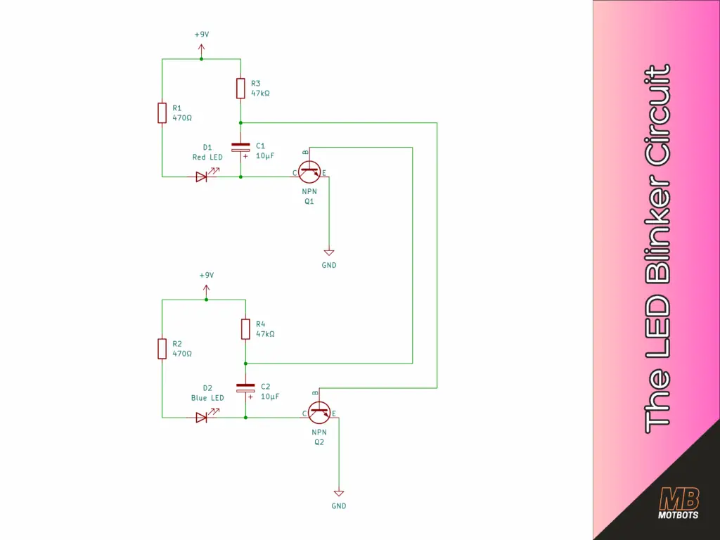
Referencing the schematic diagram of the LED blinker circuit above:
- Q1 (top) drives the red LED (D1).
- Q2 (bottom) drives the blue LED (D2).
- C1 connects Q1’s collector to Q2’s base.
- C2 connects Q2’s collector to Q1’s base.
- Each LED has its own current limiting resistor (R1, R2).
- Each transistor has a collector resistor (R3, R4).
- Each transistor is a PN2222A, NPN transitor.
- Capacitors are 10µF, polarized.
This “criss-cross” connection is what makes the circuit oscillate. We’ll get into that later, in a companion article to this one, Questions Answered on the Blinker Circuit (An Extended Topic for the LED Blinker Circuit).
⭐ How It Works in Your LED Blinker
Referencing the schematic diagram of the LED blinker circuit provided above — the circuit uses two transistors, two capacitors, and four resistors to create a little electronic argument:
- Only one transistor could be ON at a time.
- But neither one wanted to stay OFF forever.
Here’s how the sequence of events of that circuit plays out once power is connected to it (we’ll assume transistor [Q1] turns on first, before transistor [Q2]):
- Transistor Q1 turns on first (usually because of small differences in parts or wiring). This lights the red LED.
- When Q1 switches on, its collector voltage drops sharply. That drop is sent through C1, which pulls down the base of Q2, shutting Q2 off.
- While the red LED is on, C1 slowly charges through the timing resistor (R3). As it charges, Q2’s base voltage gradually rises.
- When Q2’s base voltage finally reaches the “turn-on” point, Q2 switches on and lights the blue LED.
- The exact same thing happens in reverse, but now with C2 charging through R4 to flip Q1 off.
- Back to red, then blue, then red, then blue…
This back-and-forth — driven entirely by the charging and discharging of the two capacitors — is the signature behavior of an astable multivibrator. No controller, no 555 timer — just pure, classic, unadulterated analog magic, baby.

⭐ Your Blinky Light Circuit — Explained Like You’re 7
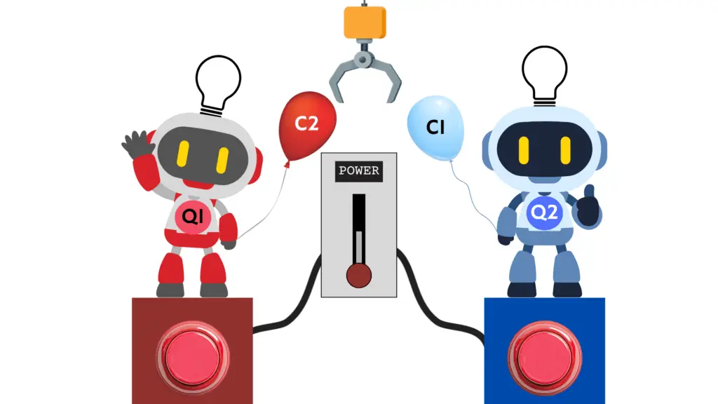
Imagine you have two little robots. One robot’s name is Q1, and the other robot’s name is Q2. Each robot has:
- a light to turn on,
- a button that turns them on,
- and a balloon that acts as a capacitor and a huge claw they use to squeeze the other’s balloon.
They live on your breadboard. And guess what? They LOVE taking turns. Here’s how they do that, step-by-step:
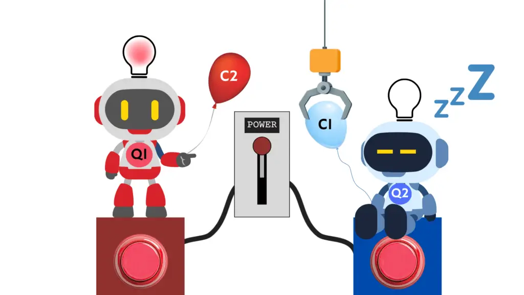
🤖🤖 Step 1 — Robot Q1 wakes up first
When you turn the power on:
- Q1 gets excited and turns on his red LED.
- When Q1 wakes up, he immediately squeezes Q2’s balloon (the capacitor, C1) with the huge claw. This squeeze tells Q2: “Hey! Don’t turn on yet! It’s MY turn!”
- So, Q2 stays OFF, and Q1 stays ON.
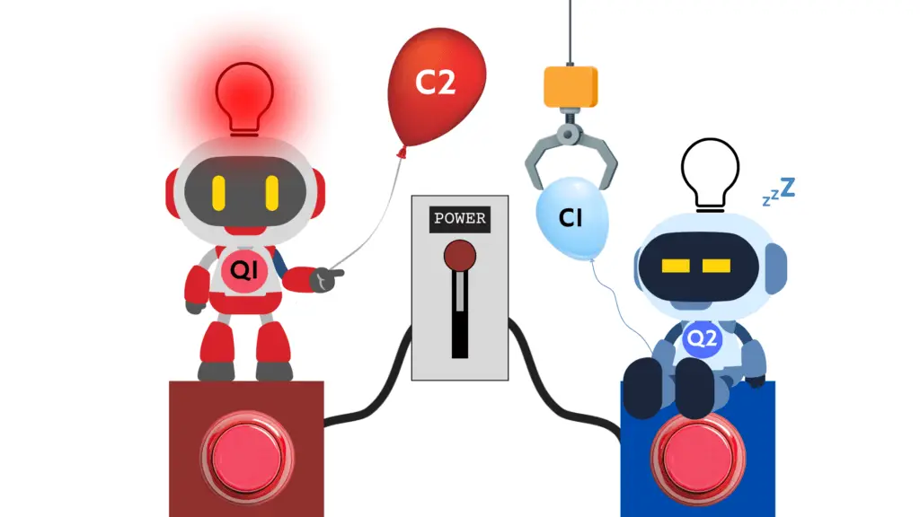
🎈 Step 2 — Q1’s balloon (capacitor, C2) slowly fills with air
While Q1 is shining his red light:
- His balloon slowly fills up (the capacitor is charging)
- As it fills up, the squeeze on Q2’s balloon gets weaker and weaker
Eventually, the balloon is full and Q1 can’t squeeze with the claw anymore. So Q2 starts waking up…
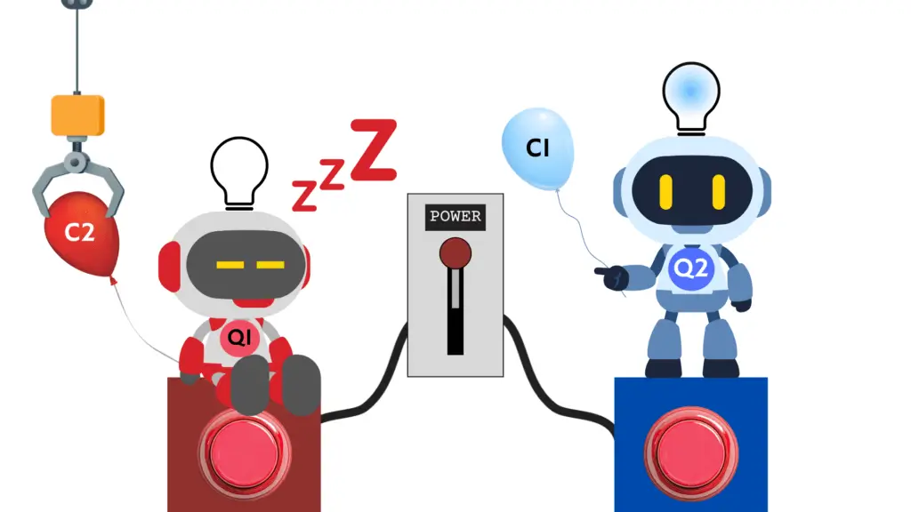
🔵 Step 3 — Q2 wakes up and turns on his blue light
As soon as Q2 wakes up:
- His blue LED turns on
- AND Q2 squeezes back on Q1’s balloon (the capacitor, C2) with the huge claw.
- This squeeze tells Q1: “HEY! Your turn is over! Go to sleep now!”
- So, Q1 turns OFF, and Q2 stays ON.
Now Q2 is enjoying his turn with his blue light shining.
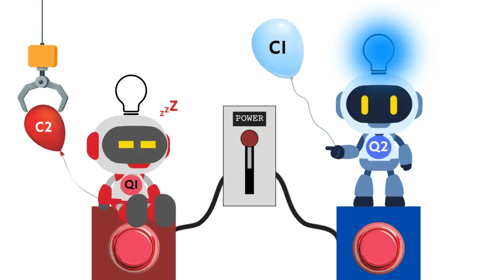
💙 Step 4 — Q2’s balloon fills up
While Q2’s blue light is on:
- His balloon (capacitor, C1) slowly fills
- His squeeze on Q1’s balloon gets weaker
- Q1 starts waking up again…
And when Q1 wakes up — he squeezes back on Q2’s balloon!
🔁 Step 5 — They take turns forever
This scenario keeps happening:
- Q1 wakes up and his red light turns on
- Q2 wakes up and his blue light turns on
- Q1 wakes up and his red light turns on
- Q2 wakes up and his blue light turns on
They squeeze each other’s balloon, one at a time, forever. This “squeezing of each other’s balloon” idea is exactly what your capacitors do in the real circuit.
⭐ The SIMPLEST Accurate Explanation of What Your Blinker Circuit Does
Let’s take a moment to use our imagination and think of the LED blinker circuit we’re trying to study here as an animation storyboard. This animation storyboard will use buckets in place of capacitors to help us understand what’s going on in this example astable multivibrator circuit — the LED blinker circuit.

Let’s observe the updated LED blinker circuit schematic above and note what has been changed for the purpose of this new explanation of the circuit:
- Notice that instead of capacitors, there are now buckets in their place in the circuit:
- Note that the transistor Q1 and the red LED will be highlighted in red when ON
- and that the transistor Q2 and the blue LED will highlighted in blue when ON.
- Also note that we’re using labels at certain points throughout the circuit to show their voltages during certain scenarios of the circuit after the 9V battery power supply is applied to the circuit:
- VC1: The voltage at the collector of transistor Q1.
- VC2: The voltage at the collector of transistor Q2.
- VB1: The voltage at the base of transistor Q1.
- VB2: The voltage at the base of transistor Q2.
We’ll pretend that the circuit is playing a game — a game of who is going to turn ON first to start a back and forth match of blinking LEDs. Is it going to be transistor Q1 to start, or transistor Q2? It’s anybody’s game in the beginning.
Now, let’s continue and observe what happens in the circuit — as it is now — once power is added to it. Let’s first start with the power being off, to be thorough, then go step-by-step in the process:
📖 Panel 1 – “Power Off: Calm Before the Blink”
The first panel of our animation storyboard shows the circuit completely grayed out — there is no power to the circuit, nothing is on, there is no electron flow through the circuit. Notice how the buckets (capacitors C1 and C2) are empty.

No current is flowing. Both transistors are off, both LEDs are dark, and both capacitors are uncharged. The circuit is “waiting” for power.
📖 Panel 2 – “Power On: Both Sides Try to Wake Up”
The battery is now ON and electrons are just now beginning to flow through the circuit from the battery’s terminals. Notice the arrows in the circuit — they show the direction of current (electron) flow:
- Some arrows show current flow from the +9V terminal of the 9V battery going through to resistor (R3) toward Q1’s collector, and through R4 toward Q2’s collector.
- More arrows are shown going to the collectors, via C1 and C2, hinting toward the bases of the transistors.
- Which transistor will turn on first? Who knows?!

As soon as 9 volts is applied, both sides of the circuit start to come alive. Tiny base currents begin to flow into both transistors through the resistors and capacitors. Both Q1 and Q2 are “trying” to turn on at the same time.
📖 Panel 3 – “Q1 Wins the Race: Red LED Turns On”
Take a look at the image below. It looks like transistor Q1, has won the race! The red LED has just started to turn on to show that it is the one that’s turning ON first — notice how the red LED and transistor Q1 are both slightly highlighted in red. Also, notice how Q2 is not highlighted showing that it is still off.
Now focus your attention to the voltage at the collector of Q1 (VC1). Its voltage reads approximately 0V.

Question: Why is the voltage at the collector of Q1 (VC1) approximately 0V?
Answer: Q1 is a BJT transistor — when it turns ON, it enters saturation.
A PN2222 (or 2N2222) transistor behaves like this:
- When the base gets enough current (even a tiny bit) the Collector–Emitter path turns into a low-resistance path to ground.
- When it’s fully ON, it enters saturation:
- Collector–Emitter voltage (VCE(sat)) becomes very small: typically 0.05V – 0.2V
So for a saturated NPN transistor the collector is at approximately 0V:
- Collector ≈ Ground (0–0.2V)
The collector is connected to the LED path, not directly to +9V. So, the path goes from +9V, through the current limiting resistor (R1), through the red LED, to the collector of Q1, through to the emitter (E), to ground.
- The collector becomes part of the ground-return path
Since the LED drops ~1.8–2.2V and the resistor drops the rest, the transistor only has ~0.1V across it.
- Thus, VC1 = the voltage at the LED’s cathode when the LED is ON, which is only slightly above ground.
Q1 turns on a little faster than Q2, because of tiny part differences. Every transistor — even two identical PN2222s from the same bag — has slight variations. These include tiny variations in:
- β (gain)
- base-emitter threshold voltage (VBE)
- internal leakage currents
- junction capacitances
- physical silicon geometry
But all this is beyond the scope of our discussion, here. We just care about who won first — transistor Q1 or transistor Q2? We see the obvious winner was Q1, since the red LED came on first.
- When Q1 turns on, it pulls its collector voltage (VC1) down close to 0V.
- Through C1, this sudden drop “kicks” Q2’s base downward (green arrow at VB2, represents base of Q2 pulled down to approximately 0V), forcing Q2 completely off.
- The result? The red LED is ON, the blue LED is OFF.

📖 Panel 4 – “Red On, Blue Held Off: C1 Slowly Charges”
Now that some time has passed, notice how the red LED is fully ON — it’s a solid red. Transistor Q1 is also clearly on, and transistor Q2 is clearly off.

Notice how the bucket C1 (capacitor C1) is partially filled (I’m using water in the bucket to represent the capacitor’s “charge level”). Also note that there’s a small green arrow pointing upward for Q2, showing that its base voltage (VB2) is slowly rising.
- With Q1 on, its collector stays low.
- C1 now slowly charges through the resistors in the circuit, and the strong negative “kick” on Q2’s base fades away.
- As C1 charges, Q2’s base (VB2) slowly rises toward the level where Q2 will eventually turn on.
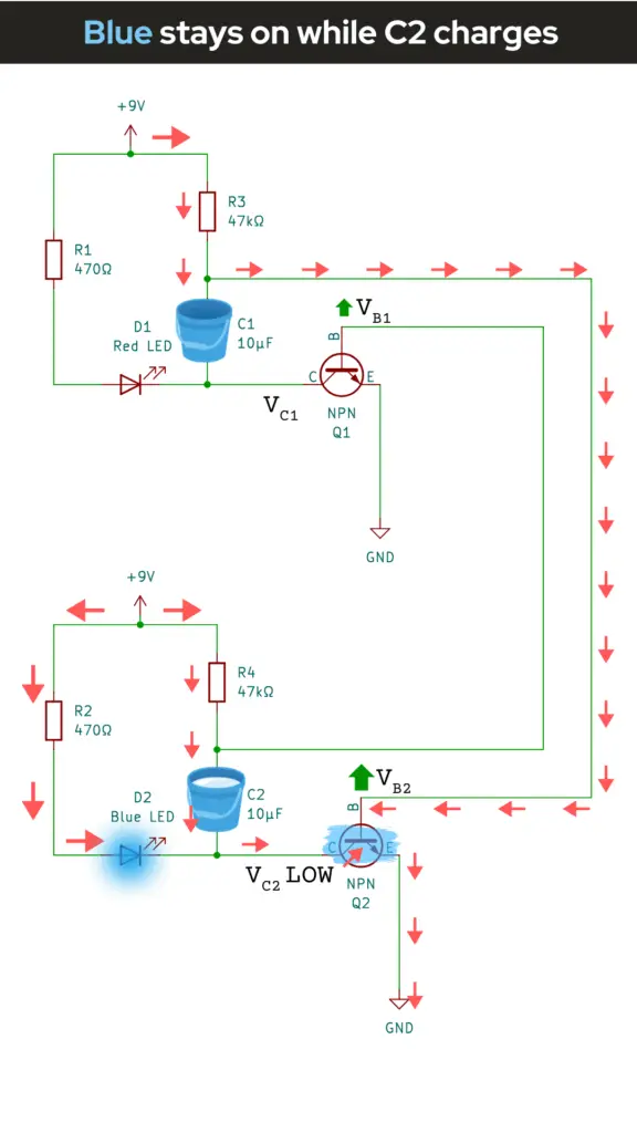
📖 Panel 5 – “Blue Side Wakes Up”
Let’s now observe what happens when the blue LED lights up. Looking at the image for Panel 5, of our animation storyboard below, notice how Q2’s base is nearing approximately 0.6-0.7V — it’s nearing the threshold.
The red LED is still on, but it’s about to lose its turn — so, it’ll start to turn off pretty soon.

As C1 finishes charging, Q2’s base voltage rises high enough to begin turning Q2 on. The circuit is at a tipping point: Q2 is about to take control from Q1.
📖 Panel 6 – “Blue Takes Over: Red is Kicked Off”
Uh-oh, it looks like the red LED has been kicked off and the blue LED has taken over. The blue LED has now begun to turn on! Notice how both Q2 and the blue LED are now both highlighted in blue to show that they’re now on in the image below for Panel 6, of our animation storyboard.
Also notice how the voltage at the collector of Q2 (VC2) has now dropped to 0V.
- When Q2 turns on, it pulls its collector voltage (VC2) down close to 0V.
- Through C2, this sudden drop “kicks” Q1’s base downward (green arrow at VB1), forcing Q1 completely off.
- The result? The blue LED is ON, the red LED is OFF.

Just to repeat — at this point in the circuit, Q2 finally turns on. Its collector (VC2) snaps down from high to low. That sudden drop passes through C2 and kicks Q1’s base downward, turning Q1 off, and Q1’s collector (VC1) rises back up toward +9V. Now the blue LED is ON, and the red LED is OFF.
📖 Panel 7 – “Blue On, Red Held Off: C2 Slowly Charges”
Now that some time has passed, the blue LED is fully on and shining bright — it’s a solid blue. Transistor Q2 is also clearly on, and transistor Q1 is clearly off.
Notice how the bucket C2 (capacitor C2) is partially filled — it’s now slowly charging, and its earlier “kick” on Q1’s base fades away.
Also note that there’s a small green arrow pointing upward for Q1, showing that its base voltage (VB1) is slowly rising.
- With Q2 on, its collector stays low.
- C2 now slowly charges through the resistors in the circuit, and the strong negative “kick” on Q1’s base fades away.
- As C2 charges, Q1’s base (VB1) slowly rises toward the level where Q1 will eventually turn on.
📖 Panel 8 – “Red Comes Back: The Cycle Repeats”
At this final panel of our animation storyboard, we start to see the cycle start again. Notice how transistor Q1 is about to turn on again and that Q2 is about to be kicked off, as shown in the image below.

Eventually, Q1 turns on again, pulling its collector low and kicking Q2 off through C1. The circuit is now back where it started, with the red LED on and blue LED off. This back-and-forth continues forever, creating the alternating blink, as observed in the LED Blinker circuit we created in How Components Work Together in Real Circuits.

Why This Circuit Is So Important
The two-transistor astable circuit you’ve created from our article How Components Work Together in Real Circuits, is more than just a blinking LED toy. It’s a foundational circuit in electronics history — one used in:
- early radios
- timing systems
- analog computers
- musical synthesizers
- blinking lights, toys, and gadgets for decades
- and even the internal logic of some older digital circuits
Today, microcontrollers might handle most timing tasks, but this little circuit still has a place in the electronics world because:
- It’s predictable
- It’s cheap
- It’s purely analog
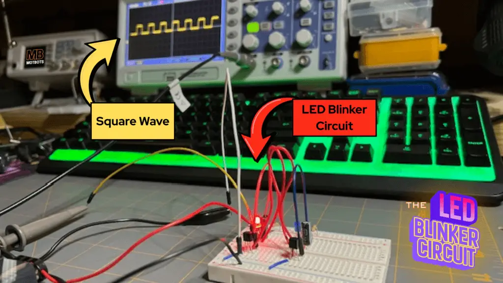
- It can generate clean square waves
- And it teaches you fundamental concepts you can’t learn from prepackaged ICs
Once you understand this circuit, oscillators, timers, and even flip-flops make a lot more sense. You’re building core electronic skills here with this circuit.
Going Further
This was like a little subseries to the Circuit Component Super Series we’ve got going on — I call it the Astable Multivibrator Subseries. This was the first article to that subseries. In the next one, we’ll dive a little deeper into the workings of our LED blinker circuit by asking some important questions, like:
- Why our circuit blinks instead of the LEDs staying on?
- What biases the bases of the transistors in our circuit?
- What determines a transistor turning on before the other if there’s no traditional base resistor?
- What does it mean when we say that a transistor’s collector “drops suddenly?”
- and MORE!
In the companion article to this one, we’ll go over in far more detail of the LED blinker circuit and how it works.
So, stick around for more on the astable multivibrator — the LED blinker circuit we made and learn more of how it works and gain a better understanding of how components work together to create fantastic things. Go further and check out the companion article to this one, Questions Answered on the Blinker Circuit (An Extended Topic for the LED Blinker Circuit).