Types of Electronic Switches and Their Characteristics
A switch in electronics is a device or component that completes a circuit electrically.
- Electrons flow from a power source through the circuit.
- Electrons need to start from the power source — flow through a circuit entirely — ending back at the power source for the circuit to be complete.
- If a switch is not yet completing the circuit — i.e. the circuit is OFF or the circuit is open at the switch — there is no flow of electrons. In other words, the electrons cannot pass through the switch to get to the rest of the circuit. There’s no current flow.
- Once a switch completes the circuit — i.e. the circuit is ON or the circuit is closed at the switch — electrons are allowed to continue their path along the circuit— tracing their way back to the power source. There is current flow.
Electronic Switches
An electronic switch is a switch that has no physical contacts or moving parts — like an electromechanical switch — that is operated by electric signals within a circuit. Electric switches are strictly controlled by active electronic components within a circuit that help send signals to the switch to automatically control it to either operate in the open position or in the closed position.
You can also learn about electromechanical switches at our Types of Electromechanical Switches and Their Configurations page here.
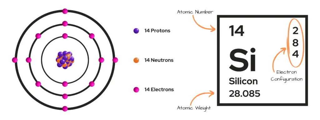
Electronic switches are often referred to as solid state switches or devices. Solid state devices are based on semiconductor material — such as silicon (Si) and germanium (Ge) — that provide a fast response and accurate operation in electronics and can be compacted into very small packages that take up little space in circuits.
There are several types of electronic switches. We will review the most common types, which include:
- Diodes
- Bipolar Junction Transistor (BJT)
- Metal-Oxide-Semiconductor Field-Effect Transistor (MOSFET)
- Insulated-Gate Bipolar Transistor (IGBT)
- Silicon Controlled Rectifier (SCR)
- Gate Turn-Off Thyristor (GTO)
- Diode AC Switch (DIAC)
- Triode AC Switch (TRIAC)
Electronic switches can come in all shapes, sizes, ratings, configurations, and types. We will not go over an exhaustive list of switches here — but mostly give an overview of them and focus only on the most commonly used switches used in industry and by hobbyists.
Electronic Switch Types
Diodes
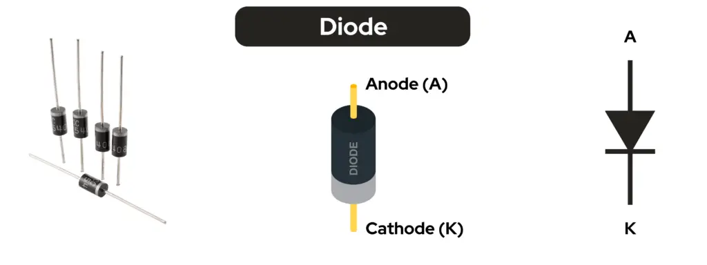
A diode is a two-terminal device consisting of two layers of semiconductor material called the n-type layer and the p-type layer.
You can actually think of a diode as a kind of check valve, in the sense that it only allows the flow of electrons in one direction. They are often used in electronics as switching components within circuits, as when they are in their forward bias state they allow the flow of current within a circuit and block the flow of current in the opposite direction or when they are in their reverse bias state.
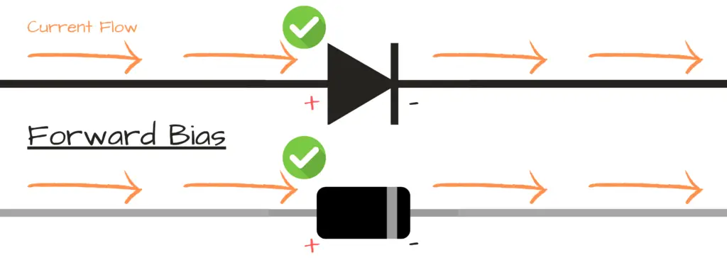
Forward Bias:
- Positive charge of power source to anode (+) of diode terminal — negative charge of power source to cathode (-) of diode terminal.
- At this state, the diode acts as a closed switch — current is allowed to flow through the diode.
Reverse Bias:
- Negative charge of power source to anode (+) of diode terminal — positive charge of power source to cathode (-) of diode terminal.
- At this state, the diode acts as an opened switch — current is not allowed to flow through the diode.

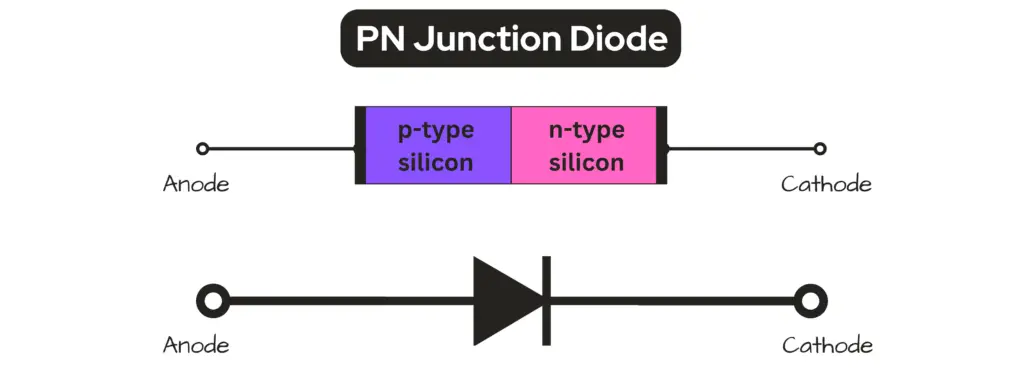
There are a variety of types of diodes, each having a specific requirement for different applications. The most basic of diodes is the P-N junction diode.
A P-N junction diode can be used as a switch utilizing its forward and reverse bias conditions.
BJT
Focus now. I said BJT, not BLT. I know you’re hungry, but I’m not talking about a yummy sandwich here.

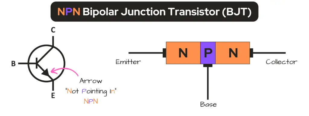
Now, I’m getting hungry. A BJT or Bipolar Junction Transistor is a three-terminal device consisting of three doped regions called a base (B), an emitter (E), and a collector (C).
The flow of current through a BJT from its collector to its emitter is controlled by current within the circuit at the base of the transistor.
The BJT is a current controlled device — in this manner, the BJT acts as a switch when a current is applied to its base terminal— therefore, closing the circuit — or allowing the flow of current through the BJT from the collector to the emitter of the transistor.
A BJT uses both electrons and holes (the absence of electrons) for electrical conduction. The construction of a BJT allows for electrons to leave the n-type region of the transistor, let’s say, and for the electrons to fill the “holes” in the p-type region of the transistor— creating the flow of current.
Based on their construction and operation — BJTs can come in a couple of flavors:
NPN Transistor
- In the construction of the NPN transistor, the collector and the emitter are of the n-type material — the base is of the p-type material.
- NPN transistors are preferred over PNP transistors due to their improved performance characteristics resulting from the higher mobility of electrons as compared to holes.
PNP Transistor
- In the construction of the PNP transistor, the collector and the emitter are of the p-type material — the base is of the n-type material.
- PNP transistors are similar to NPN transistors in the way they perform — the differences are that their voltage polarities and current directions are reversed.

MOSFET

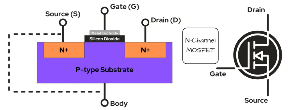
No, this is not some has-been rock band. The Metal-Oxide-Semiconductor Field-Effect Transistor — or MOSFET, is a field-effect transistor with three terminals — a source (S), a gate (G) and a drain (D).
A field-effect transistor — or FET, is a type of transistor that uses an electric field to control the flow of current and the MOSFET is the most common type of FET.
The gate terminal of the MOSFET is what consists of a metal-oxide, such as silicon dioxide (SiO₂), which acts as an insulator. The gate terminal is separated from the main current-carrying channel by the thin layer of silicon dioxide, which allows the Gate Voltage (VG) to create an electric field controls the conductivity of the channel.
The MOSFET is a voltage controlled device — in this manner, if we apply a voltage to the gate terminal of the MOSFET, then it acts as an electrical switch controlling the amount of current flow between the source terminal and the drain terminal.
Based on their construction and operation — MOSFETs also come in a couple of flavors:
N-channel MOSFET
- In this type of MOSFET, the channel is composed of a majority of electrons as its current carriers.
- A positive voltage is applied to the Gate to create the conductive channel — activating the MOSFET — having the majority of its current flow as electrons through the channel.
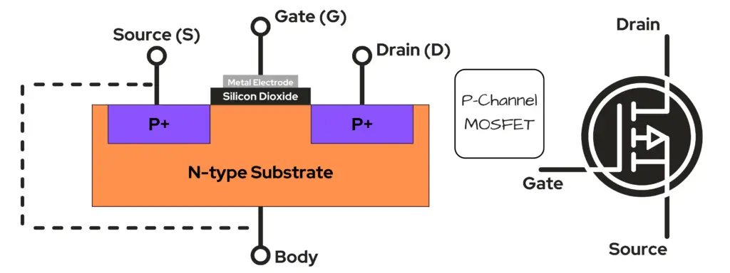
P-channel MOSFET
- In this type of MOSFET, the channel is composed of a majority of holes (remember, holes are the absence of electrons) as its current carriers.
- A negative voltage is applied to the Gate to create the conductive channel — activating the MOSFET — having the majority of its current flow as holes through the channel.
IGBT

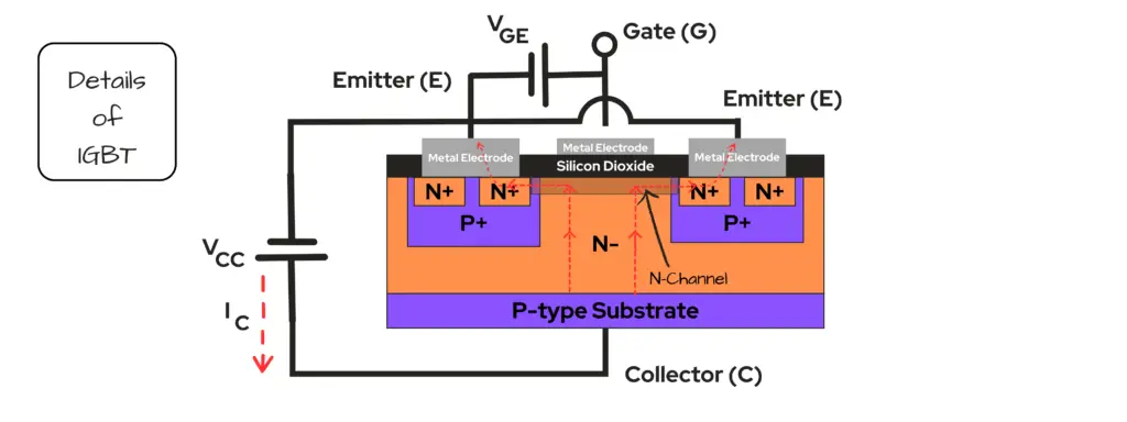
Not the online database for movies and TV shows. The Insulated Gate Bipolar Transistor is a three terminal high speed switching device that brings the advantages of both the BJT and the MOSFET together into one powerful and efficient package.
The IGBT is similar to the BJT in the sense that it is a sandwich of four alternating layers of p-type and n-type semiconductor material — yet it has an insulated gate structure similar to the MOSFET.
Also, like the MOSFET — the IGBT is a voltage controlled device with a lower voltage drop for its ON state. If we apply a positive voltage across its gate (G) and emitter (E), the IGBT becomes in its ON state.
The IGBT can be used as both an ON and an OFF switch — depending on its Gate-Emitter Voltage (VGE), therefore controlling its Collector Current (IC):
- OFF: When VGE = 0, then IC = 0. The device is like an open switch.
- ON: When the Gate-Emitter Voltage exceeds the threshold limit, VGE > VTH, then IC increases and the device acts as a closed switch.
SCR

Not to be confused with VCR, the SCR or Silicon Controlled Rectifier — a.k.a. the Thyristor — is like a four-layer cake, but instead of layers of sugar filled flour and eggs, the SCR is composed of p-type and n-type semiconductor material — known as a PNPN device.
The SCR is a three terminal device consisting of a gate (G), anode (A) and cathode (K) — and is used as a switching device. It can convert AC into DC whose power can be controlled.
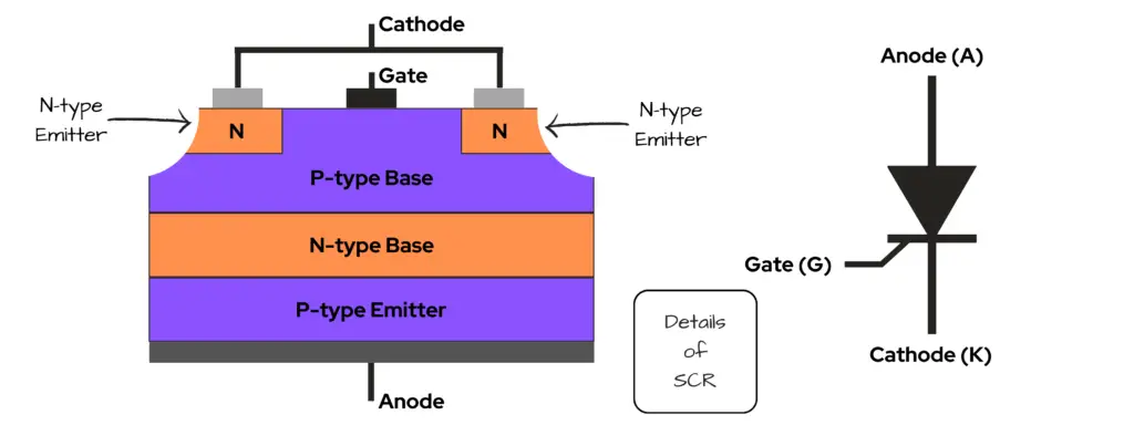
The way the thyristor or SCR differentiates itself from other types of electronic switches is that it is considered a latching device — meaning that it only needs a trigger pulse or lightning-fast voltage jolt for a brief moment to start conduction — this makes the SCR a voltage-controlled device.
Once the SCR has been “latched” or has started its current conduction, it will continue to be in its conduction state until the charge flow between the anode and cathode stops. This means — once it stops — in order to resume current conduction again it will need another trigger pulse.
You can think of “latching” as like when you latch a gate to a fence. If the gate is open, an ant on top of the fence can’t continue down the fence line. Once the gate is latched — or closed — a connection is made allowing the ant to continue, until someone comes along to open the gate again. Using our analogy here, we can think of the fence as the conductor – allowing a path for the ant to walk along. We can think of the gate as being a switch and the ant and his friends as being the current. To resume current conduction, you have to yell at the person who left the gate open, “Hey! Close the gate!”

GTO

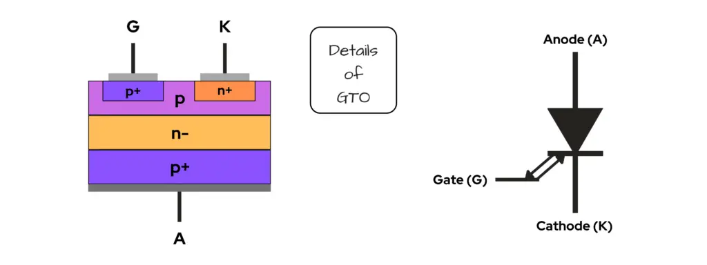
Not the GTO you’re thinking of. The Gate Turn-Off Thyristor — similar to the SCR — also consists of four alternating layers of n-type and p-type materials — also known as an NPNP device, but where it defers from an ordinary thyristor is that it has an n+ buffer layer.
The GTO is a fully controlled unidirectional switching device with an n+ buffer layer added to its cathode (+) side — what this does is to reduce the device’s turn-off time as well as to increase its ability to be managed.
- ON: Similar to the SCR, the GTO is turned on by applying a positive pulse to the gate (G) terminal relative to the cathode (-) — this makes the GTO a voltage-controlled device. The positive pulse to the gate causes the GTO to become forward-bias — therefore, creating current flow through the device — turning it ON.
- OFF: The GTO is named for its ability to turn OFF through the gate (G) terminal. To turn OFF the GTO a negative pulse is applied to the gate terminal.
DIAC
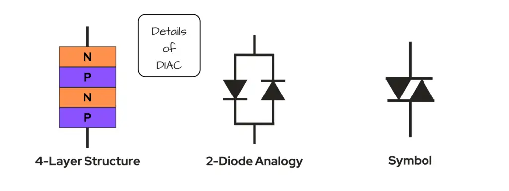
The Diode for Alternating Current is a two-terminal bidirectional semiconductor device used to trigger a thyristor or TRIAC.
Being bidirectional means that the DIAC can be operated in either direction — no need for terminal identification.
When a voltage that is greater than its break-over voltage (VBO) is applied to a DIAC, it can either operate in a forward blocking or reverse blocking state. Its main function is to help trigger and activate a TRIAC to conduct symmetrical switching operations.
TRIAC
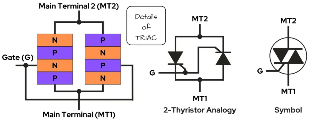
A Triode for Alternating Current is a three-terminal bidirectional semiconductor device used as a switch that is capable of conducting in both directions.
Often used for power electronics, the TRIAC in these cases are used for current flow control. A unique characteristic about TRIACs is that they can switch both halves of an AC cycle — meaning both the positive and negative cycle — making it a useful component to control AC power.
The TRIAC is basically composed of back-to-back SCRs constructed into a three-terminal package used for regulating power in AC circuits.
Review of Electronic Switch Types
| Type | Characteristics | Description | Properties | Applications |
| Diode | P-N Junction | A two-terminal semiconductor device that acts as a check valve for current flow within a circuit. | Must be forward bias to allow the flow of current. | Rectification, signal demodulation, clipping, clamping |
| BJT | NPN and PNP | A three-terminal current-controlled device that is activated via current at its base terminal to allow the flow of current from its collector to its emitter terminals. | Current-controlled device | Digital switch, amplifier, electronic switch, converters |
| MOSFET | N-channel and P-channel | A three-terminal voltage-controlled device that is activated via current at its gate terminal, creating an electric field to allow the flow of current from its source to it drain terminal. | Voltage-controlled device | Switching, amplifying signals, regulation for DC motors |
| IGBT | Has four alternating layers of p-type and n-type semiconductor material. | A three-terminal high-speed switching device that brings the advantages of both BJT and the MOSFET together into one powerful and efficient package. | Voltage-controlled device | Switch Mode Power Supply (SMPS), Uninterrupted Power Supply (UPS), speed control in AC and DC motor drives. |
| SCR | Has four alternating layers of p-type and n-type semiconductor material. | A three-terminal switching device that can convert AC into DC whose power can be controlled. | A voltage-controlled device that needs a trigger pulse to start current conduction, known as latching. | Switching, power control, over-voltage protection, pulse circuits |
| GTO | Has four alternating layers of p-type and n-type semiconductor material. | A three-terminal switching device. | A voltage-controlled device that needs a positive pulse to the gate terminal to start conduction. | Switching Mode Power Supplies (SMPS), AC and DC motor drives |
| DIAC | Has two-terminals and operates bidirectionally. | A two-terminal bi-directional semiconductor device used to trigger a thyristor or TRIAC. | Its main function is to help trigger and activate a TRIAC to conduct symmetrical switching operations. | Trigger a TRIAC |
| TRIAC | Has three-terminals and operates bidirectionally. | A three-terminal package used for regulating power in AC circuits. | Composed of back-to-back SCRs constructed into a three-terminal package used for regulating power in AC circuits. | Switching applications, AC power control |
Conclusion
We have gone over several types of electronic switches and their functions within this blog post. We have learned that electronic switches play a critical role in many, if not all circuits. We’ve learned that electronic switches have an ability to be controlled by current and/or voltage in a circuit to provide electrical energy and unique functionality elsewhere in the circuit.
There is much more to electronic switches and there are many other kinds of switches out in the world, but what we’ve reviewed here is what are commonly used and recognized by most electronics hobbyists and what are used in a variety of industries.