Circuit Theory: Ideal and Practical Voltage Sources
An ideal voltage source is a source of constant voltage to a system, independent of any fluctuations of current. An ideal voltage source provides this constant voltage with 100% efficiency — it has a series internal resistance with a value of zero.
A practical voltage source is a device that supplies voltage to a system, yet unlike an ideal voltage source, has some internal resistance in series within itself — it cannot provide its full voltage potential due to its internal resistance, therefore it is not 100% efficient.
What’s a Source?
A source is any device that delivers energy into to a system — whereas, a device that extracts or consumes energy from a system is known as an electrical load. If we consider an electrical circuit as our system, we can think of the source as being a 9V battery, and an electrical load as being a speaker, for example.
Sources convert mechanical, chemical, thermal and other forms of energy into electrical energy — such as a 9V battery converting chemical energy into electrical energy. A source is considered to be an active element that generates electrical energy in some way.
Preliminary Concepts You May Want to Review
Before continuing on with our discussion of ideal voltage sources, you may want to consider looking further into the circuit theory of active and passive components here. Having a good understanding of active and passive components — and what they are — will greatly increase your understanding of voltage sources.
A Quick Recollection of Ohm’s Law and Resistance
We just need to quickly refresh our memory of Ohm’s law before continuing. If you need a thorough explanation of Ohm’s Law, then check out our page titled “Ohm’s Law: Simply Explained” here. Otherwise, the following is a quick overview of the concept of Ohm’s Law.
Ohm’s law is a relation between voltage, current and resistance — it states that for a given resistance and an electric current flowing through that resistance, there is a voltage potential across that resistance.
The formula for Ohm’s Law shows that for a given resistance, the product of the resistance (R) and the current (I) are proportional to (equal to) the voltage potential (V) across that resistance:
\begin{equation}
V = IR
\end{equation}
A resistance or resistor (R) is an element in a circuit that opposes the flow of current within a circuit. A resistor is a passive element that dissipates energy in the form of heat.

Ohm’s Law describes the I-V characteristics for a resistor:
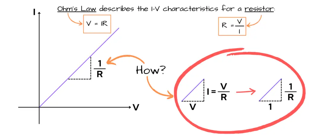
The purple line shown in the image of the I-V characteristics for a resistor above is at a 45 degree angle. The two sides of the triangle formed in the image above (dashed lines) states that for every unit over in volts, there is an increase in current by a unit of 1⁄R — said “one over R” — where resistance or R is being held constant — meaning R doesn’t change.
This is clearly stated in Ohm’s Law as I = V⁄R. An increase in voltage increases the current, when resistance (R) is held constant.
Ideal Voltage Source
It was briefly mentioned earlier that an active element is the circuit component that supplies energy to other circuit components — it delivers power or energy to a circuit. Again, I suggest you read up on active and passive elements here, if you’re not familiar with these concepts.
An ideal voltage source is a device capable of supplying a constant voltage to a circuit with respect to time, and is free from the influence of current of which the circuit draws. In short, an ideal voltage source delivers a prescribed voltage independent of the current flowing through the circuit it is associated with.

An alternative to the time-varying voltage source is the constant voltage source symbol as shown below:

Characteristics of an Ideal Voltage Source
- An ideal voltage source refers to a source that consistently maintains a constant voltage supply to a circuit, regardless of the amount of current drawn by the circuit.
- What this means is that no matter the resistance in a circuit — such as in a load —or its current draw, the ideal voltage source will always provide a constant voltage.
- An ideal voltage source acts to provide 100% efficiency of voltage supply — meaning that the source has zero or no internal resistance.
- The internal resistance of an ideal voltage source is zero and in series with the source.
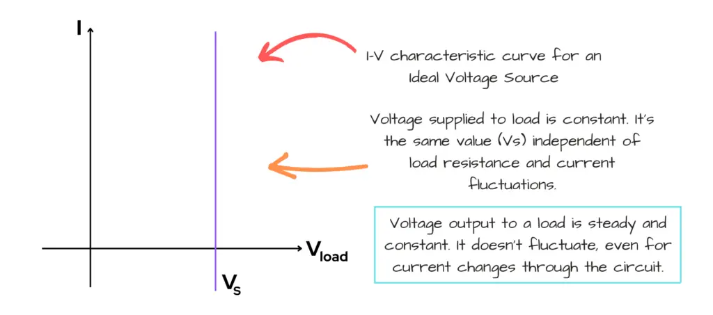
We can also look at the relation between the ideal voltage source (VS) and the resistance of the circuit:

Note that when resistance (R) is zero, the voltage is still at the source voltage (VS), as seen in the R vs. V characteristic curve image above.
Even if there were fluctuations in load resistance, the source voltage output stays constant for an ideal voltage source, as seen in the R vs. V characteristic curve image above.
What Does It Mean to Have Zero Internal Resistance?
As stated earlier, an ideal voltage source acts to provide 100% efficiency of voltage supply to a circuit — it has zero internal resistance. Let’s take a look at the following circuit with a labeled internal resistance (Rin) of a battery:

In order to provide this so-called 100% efficiency, there can be no internal resistance to provide the entire source voltage (VS = 9V) across the resistive load of 8Ω in the circuit — hence, an ideal voltage source.
\begin{equation}
V_{load}\space =\space V_{AB}\space =\space V_S\space =\space 9V
\end{equation}
Again, having zero internal resisance (Rin = 0Ω) in the battery means that the source, in theory, could provide all of its voltage potential to the load. There’s no such thing!
Looking Further Into the Details
Let’s look at the image of the ideal voltage source again:

Let’s review what our ideal voltage source circuit is telling us from the image above:
- Our ideal voltage source has zero internal resistance (Rin = 0Ω) and a given source voltage (VS) value of 9V.
- Note that the ideal voltage source, let’s call it Videal, is the source voltage with no internal resistance (Rin = 0Ω). Using Ohm’s Law, we can say Videal= Irin.
- So, the source voltage is a combination of the ideal voltage (Videal) and the voltage across the terminals A and B (VAB) — the voltage across the load. Using the fact that the sum of voltages in a closed, non-branching loop is equal to the source voltage — we add the two values to get the source voltage: VS = VAB + Videal
- The load resistance (Rload) is a resistance connected in series with our source having zero internal resistance. The load resistance is connected across the terminals A and B — so its voltage potential should be equal to the voltage across the terminals VAB. Review our page on parallel circuits here if you are confused by this statement.
- A current (IS) is shown flowing through the circuit.
If our source is ideal, that means that the voltage across the terminals A and B must be always constant and equal to the battery source voltage of VS — this must be true no matter the value of current (IS).
The statement “this must be true no matter the value of current (IS)” is telling us that the internal resistance (Rin) of the source voltage must be zero — i.e. ideal.
- Why?
- Because, look at the circuit theory of the sum of voltages in series in a loop — according to our circuit above, for the voltage across the terminals A and B (VAB) to be equal to the battery source voltage (VS), then VAB must equal to the difference of the battery source voltage (VS) and the ideal source voltage (Videal), of which has an internal resistance of zero.
- Why?
- We have to consider the battery source voltage as a whole — as stated above, as being:
\begin{equation}
V_S\space =\space V_{AB}\space +\space V_{ideal}
\end{equation}
where the ideal voltage has no internal resistance. So, the voltage across terminals A and B (VAB) must equal to the source voltage of the battery (VS) minus what makes up the ideal voltage source, which includes the current (IS) and internal resistance (Rin):
\begin{equation}
V_{AB}\space =\space V_S\space -\space V_{ideal}
\end{equation}
\begin{equation}
V_{AB}\space =\space V_S\space -\space I_SR_{in}
\end{equation}
\begin{equation}
V_{AB}\space =\space 9V\space -\space I_S(0Ω)
\end{equation}
\begin{equation}
V_{AB}\space =\space 9V\space -\space 0
\end{equation}
\begin{equation}
\boxed{V_{AB}\space =\space 9V}
\end{equation}
Practical Voltage Source
In reality, there’s always some sort of internal resistance in a voltage source. These losses due to the internal resistance comes from the physical makeup of the source itself — this is what’s called a practical voltage source.
A practical voltage source is a device that supplies voltage to a circuit, yet unlike an ideal voltage source, it has some internal resistance in series within itself. This series resistance causes a voltage drop when current passes through the source causing slight variations in their voltages.
Practical Voltage Source Example:
Let’s say you measured a battery you opened from a package that was labeled to be 9V. You take a multimeter to measure its voltage potential across its terminals and it reads 9.26V.

Now, let’s say you set up a load consisting of a red LED and a 560Ω resistor in series to a breadboard. You connect your power source (the 9V battery you measured) and connect your multimeter across both the resistor and LED that are in series — you’re including the entire load here which, if the battery were an ideal voltage source should read 9.26V across the load. But, the multimeter is measuring 9.16V, not 9.26V.
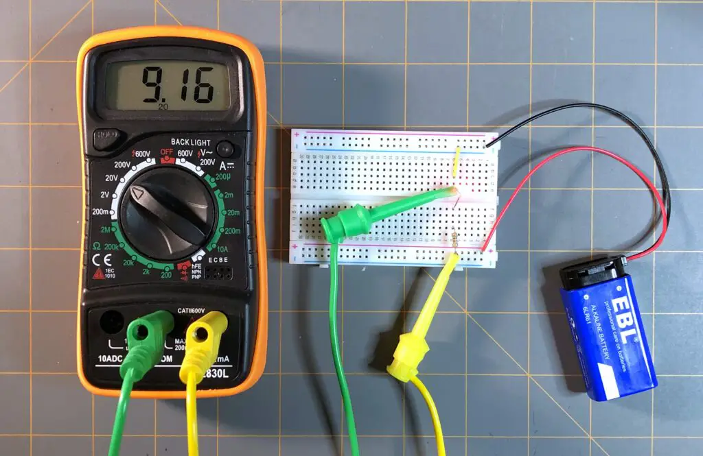
- What happened? Why is the multimeter showing 9.16V across the load and not showing 9.26V?
- This means that the battery is not truly an ideal voltage source. It cannot deliver the full potential of 9.26V, measured by our multimeter. If it could, our multimeter should also measure 9.26V across our load consisting of both the LED and resistor in series, no matter there combined resistance and current flowing through them. This means there is some internal resistance within the battery itself — preventing it from delivering the full voltage potential of 9.26V.
What Do We Do When Calculating for Internal Resistances?
We don’t. When designing circuits or doing circuit calculations, we almost always consider any voltage source in our circuit to be ideal. This makes calculations much easier, because it’s not always possible to know what the internal resistances are for our sources.
- Won’t calculating our circuits to always have ideal voltage sources provide us with incorrect figures of our practical circuits?
- Yes, but the differences in values are usually small enough to not really matter. You’ll learn that in engineering that the term “close enough” does just fine for most products.
Conclusion
We stared off going over sources and what they are. You learned that a source is any device that delivers energy into a system. We further expanded the idea of sources into their ideal and practical situations.
You learned that an ideal voltage source is a type of source that provides all of its voltage potential across its terminals — that it is a source with no internal resistance. You learned that a practical voltage source is the real world version of a source, which does consider its internal resistance and that the potential across its terminals aren’t necessarily the same value shown across a load.
Next, our discussion continues on ideal and practical current sources of which you can learn about on our page entitled Circuit Theory: Ideal and Practical Current Sources here. Remember, keep at it and stay motivated!