live_tv
Livestream Starting Soon
00
Hours
:
00
Minutes
:
00
Seconds
Up next in 10

The Layout of the Power Supply Components - The Ultimate DIY 3220-Point Breadboard
Oct 11, 2024

This is a supplemental video to our page titled "The Ultimate DIY 3220-Point Breadboard".
The purpose of this video is to show the process of laying out the components that we will need to drill holes for on our art box carrying case we're using for our Ultimate DIY 3220-Point Breadboard project. You may choose how you want your breadboard power supply components to be laid out on your own art box, or you may follow along as how I've laid out mine. We will do this as part of The Ultimate DIY 3220-Point Breadboard project done on our website (info below).
PARTS LIST:
830-Point Solderless Breadboards: https://amzn.to/3ZHa5Hy
Deluxe Art Set Box 14.5”x9”x1.75”: https://amzn.to/3XWtuDf
TOOLS USED:
Cordless Drill: https://amzn.to/4ehNuFZ
Rotary Tool: https://amzn.to/3XJxwxk
You can find all the "How-To" information to build this project for yourself and the complete parts list at our website:
https://motbots.com/the-ultimate-diy-3220-point-breadboard/
To see the entire build process from our videos, go to our playlist entitled "The Ultimate DIY 3220-Point Breadboard":
https://www.youtube.com/playlist?list=PLXoXZro7IN0e-cALhowH6yLL0Qi-3BJhe
Video for Our Website Page: "The Ultimate DIY 3220-Point Breadboard"
Page URL: https://motbots.com/the-ultimate-diy-3220-point-breadboard/
Show More Show Less View Video Transcript
0:00
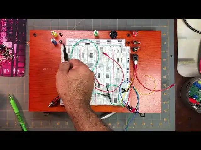
Okay, now we're at the point in the project for our DIY 3,220 point breadboard project
0:13
where we want to start laying out where the holes will need to be drilled into our art box carrying case
0:24
So on a previous step, we attached our 3,220 point breadboard and the power rails on to the lid of the art box carrying case
0:42
And, of course, in earlier steps, we prepped our switches, switch one, two, and three
0:50
and now we can see some other items here there's the the blue binding post here they're
1:03
upside down by the way all of the binding post are upside down but we have the
1:07
blue one that represents the nine-volt output we have the yellow binding post that
1:17
represents the six-volt output the green which represents the common ground. This red binding post which is for the
1:30
bench top power supply input. We have this smaller red binding post that is for the
1:46
nine-bolt battery power supply output. and the 9-volt battery power supply ground is this other smaller binding post that's the color black
2:00
I'm using these two smaller binding posts because I had them. I'm just using binding posts that I had available
2:11
What would be better than these type of binding posts, which they look like this
2:17
you know your typical binding post and you get some light here what would be
2:25
what would be better than these types of binding post would be like a flush mount
2:30
or panel mount binding posts where they'd be very low profile to the to the box
2:40
here but I don't have any I've got several of these types of
2:47
taller binding posts like this so I'm using these in different colors and I decided to use these two smaller binding posts that I had available I had them lying around
3:04
specifically for the 9-volt battery power supply for the breadboard this rubber grommet here I'm going to use a
3:17
as where my output pin for the bench top power supply, the positive supply is gonna come out of
3:29
And it's just going to be a wire with a pin at the end of it that I can pin into the positive power
3:40
or the positive side of the power rails here. These black, little LED panel mount pieces are on here
3:57
Let me get one so you can see it up close. I don't want to mess up what I've already laid out here
4:02
because I spent way too much time trying to figure out how I wanted to lay out everything And I tried to lay out everything on the box The best that I could that would be easy to see what going on to see what on what may be more practical and
4:28
ergonomic. But you can lay out your breadboard any way you'd like. I'm just laying mine out the way
4:37
that you see it at least that's how I plan to do it so here's one of those
4:42
let me get some extra light here here's one of those LED it's just a basic
5:03
panel mount which will kind of make the LEDs not so much sit flush but sit down
5:12
into the board a little bit then sticking out but I'm using those in some
5:23
strategic locations on my setup here so I said that I'll start from right to
5:31
left this time so I said said here was for these binding posts here or for my 9 volt battery power supply
5:42
So this plastic LED panel mount will be the white LED that will be using to show that that
5:57
9 volt battery power supply is on when switch 3 is flit
6:02
is flipped on and just to let you know we're referring to the schematic here that I
6:14
put on the website for this project at motbots.com so this is for the white
6:29
LED for the battery power the nine-volt battery power to show when it's on that's the indicator light the white one this is for the indicator
6:38
light for when the bench top power supply is on that's the red LED this one here
6:48
is for the yellow indicator light and it's associated with when the six-bolt power supply
6:57
is on and this one here is for the blue LED indicator light
7:02
which comes on when you're using or when the 9 volt power supply is on and then this
7:10
this one over here is for the green LED indicator light for when we're using the
7:22
12 volt charge adapter this happens to be a flush mount or panel mount or panel
7:32
mount charger adapter for the female end so you'd stick your adapter in there
7:41
let me get the adapter real quick so you can see I'm sure you know how it works
7:47
but I'll just go ahead and show you here real quick so it's it's for where we'll
7:58
plug in the adapter like so and this is the panel mount one, so I'll end up mounting it on the side here on the top half of the box
8:13
And that what this green LED indicator light will be for is when we using the 12 volt charge adapter for our power supply And I have the two toggle switches here This is switch one and this is switch two
8:35
And I kind of wanted to put them where the toggle switches are mounted on the front side here
8:44
kind of on either side of the handle here. So there'll be
8:49
sticking out kind of like that and then you can control them from here and I figured
8:58
that may be a little better than instead of having everything on top of here. Another
9:06
thing that I had to consider this is totally up to you as well but I want to put
9:12
labels on everything and I had to set up everything in anticipation on where labels
9:19
we're going to be placed. So I'm thinking I want to put labels for items on this side
9:26
on the right side, maybe put the label for this grommet on its left side and the label for the common ground
9:36
on its left side, and then the things that are on the left side, the labels on the left
9:41
And then for this indicator light, I might put its label below it
9:46
And the labels for these. switch is one and two since they're going to be mounted. I'm wanting to mount them on the front here
9:55
I'll put their labels right here so it's easy to see what's happening on depending on what direction you're turning the toggle switch like so
10:10
So if their labels were on top it'd be easy to see. And I wanted to keep that idea for
10:19
being able to easily see what's going on by keeping the indicator LED lights kind of compacted in and not all over the place and also right next to
10:33
whether what what the lights are supposed to be representing. So again, you don't have to set yours up like mine. You can, you know
10:49
layout your components the way you want to, but this is how I think I'm going to do mine
10:55
So the next thing that I'll need to do is that once I'm good and ready and I have the layout that I want set
11:06
I'm going to start kind of rough measuring and marking where everything's going to go, maybe
11:13
even labeling where everything is going, and then I'll start marking where the holes now
11:19
need to be and then I'll get my tools and start drilling holes and that'll be in the next
11:28
video okay at this point I've made my rough measurements on everything on where the
11:43
placement of all of the items are going to go on the
11:49
box I use my calipers to measure out the sizes of everything that would need to be drilled out
12:06
So I would just use my calipers to measure different items such as the studs on these
12:18
binding posts making sure that I'm measuring what needs to be measured not like
12:30
this one I would need to measure out here because this section of the post needs to go all the way down inside the box where
12:42
this part here will sit on top of the box flush sticking out like that. You just need to be
12:51
aware of what you need to measure. Having a good calipers helps out a lot on how large your
13:02
holes need to be or how close you can get for the size of the holes that you need to drill
13:09
So I just use some pencil marks on here just to kind of roughly mark out and measure where I wanted
13:23
things to go. As I said, I want to put the toggle switches, switches one and two on the front end of the box
13:32
on the same side as the handle. These are the other components here
13:40
I want to put the input DC jack, that panel mount right there, this guy
13:49
I want to put it in here. So you can lay yours out however you want
13:56
You can be more exact than I am or not. It's up to you
14:02
your project. So now I'm just going to drill the holes and we'll go from there
14:19
Okay, now that I've made a royal mess of things, I think I have everything on here that needs to be on here
14:28
I've got all my binding posts here, my number three switch or switch three, which controls or will control when everything's hooked up the 9 volt battery supply
14:47
I have the two toggle switches here that are switch one and switch two
14:55
that will eventually control the separate power supplies in the 9 and 6 volt power supplies
15:10
I've got the LED panel mounts. I've got this rubber grommet in that will eventually have a wire lead coming out with a pen
15:25
at the end of it that will allow you to attach to the positive rails for the power rails
15:34
It's the positive output from the bench top supply. This is the input
15:46
I've got the DC power adapter panel mount here. be 12 volts DC coming in from a 12 volt charge adapter
16:00
And now we have our art box carrying case for our 3,220 point breadboard, all set up and ready to go
16:16
So the next thing that we'll need to do is start doing the circuitry for the NCHA
16:23
for the insides. And we'll connect all these switch wires to it
16:30
and then connect other wires to the binding posts and to the 12-volt charge adapter
16:40
And then we'll be that much closer to being finished with this project
#Computer Hardware
#Computer Components
#Power Supplies