Up next in 10


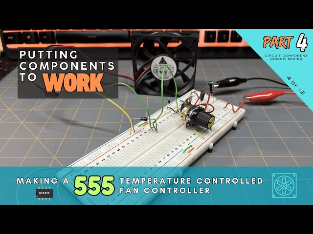
This is a companion video for our Circuit Component Super Series at Motbots.com. In this video we make a 555 Temperature-Controlled Fan Controller from the circuit build instructional content in Part 4 of our series titled, "Putting Components to Work: Making a 555 Temperature Controlled Fan Controller."
It's encouraged that you go check out our Circuit Component Super Series, particularly "Putting Components to Work," to gain a better understanding of how the components used for this circuit work together to control a 12VDC brushless fan using a 555 timer. (Link below)
Video for Our Website Page: "Putting Components to Work: Making a 555 Temperature-Controlled Fan Controller"
Page URL: https://motbots.com/putting-components-to-work-making-a-555-temperature-controlled-fan-controller/
Description: This is a supplemental video for a post made on our website.
Website: https://motbots.com
_________ PROJECT INFO _________
🛠️ Parts List
https://motbots.com/putting-components-to-work-making-a-555-temperature-controlled-fan-controller/#Parts_List
🗺️ Schematic for the 555 Temperature-Controlled Fan Controller https://motbots.com/putting-components-to-work-making-a-555-temperature-controlled-fan-controller/#555-temp-control-fan-schematic
_________ RESOURCES _________
⚡️ Circuit Component Super Series
Show More Show Less View Video Transcript
0:00
Hello and welcome back to the workbench. I'm Dustin with Mopbots and today we're going to create a true sensor to logic
0:07
to actuator system. In this project, we'll build a circuit that reacts to the real world instead of blinking LEDs like
0:15
we did in the previous project. This circuit senses temperature and makes a decision just like real electronics
0:21
inside robots, computers, and machines.
0:32
If you've completed the LED blinker circuit from part three, congratulations. You've already built a
0:38
dynamic circuit. Now it's time to level up your game with this circuit. So for this project, we're putting together
0:43
what I call the 555 temperature controlled fan controller using a thermister, 555 timer, and a MOSFET
0:50
along with some other necessary components. The 555 temperature controlled fan controller once finished
0:56
will be a circuit that cools when the temperature rises with the use of a 12volt DC fan and a potentiometer. The
1:03
DC fan turns on when the circuit gets warm and turns off when it cools down. The fan stays off when the circuit is
1:10
cool until a certain threshold is reached when the circuit warms up. Then the fan turns on. The fan stays on when
1:17
the circuit is warm until a certain threshold is reached when the circuit cools down. then the fan turns off. A
1:23
potentiometer lets you adjust the temperature threshold. It uses a 555 timer as a Schmidt trigger comparator so
1:31
it doesn't chatter on and off around the threshold. A MOSFET handles the fan
1:36
current safely. Unlike a simple comparator, a Schmidt trigger has two
1:41
voltage thresholds. An upper threshold where the output switches on and a lower
1:46
threshold where the output switches off. Between these two thresholds, the output does not change even if the input
1:53
wiggles around. This gap between thresholds is called hysteresus. Hysteresus is a small intentional dead
2:01
zone that prevents a circuit from changing its output too easily. Instead
2:06
of switching on and off at the same point, a circuit with hysteresus turns on at one level and turns off at a
2:12
different level. This separation between switching points makes the circuit stable and predictable. For this
2:19
project, we're using a thermister as part of the sensor node of the circuit. A thermister is a special type of
2:26
resistor whose resistance changes with temperature. We're going to use a 10K
2:32
NTC thermister, where NTC stands for negative temperature coefficient,
2:38
meaning the resistance decreases as temperature increases. A thermister by itself only changes resistance, not
2:45
voltage. To make it useful, we place it in a voltage divider with a regular resistor. As temperature rises, the
2:52
thermister's resistance drops. This causes the divider's output voltage to change. That changing voltage represents
3:00
the current temperature. Heat becomes an electrical signal that the circuit can
3:05
understand. This video here is not meant to walk you through with how and where to place your components and jumper
3:11
wires onto your breadboard. I proceeded with this breadboard build like I do with many others with no particular
3:17
planning involved. All I did was follow my schematic diagram as I wanted the circuit to be, did the best I could to
3:24
follow the diagram, and placed my components as best as possible on my breadboard. This is a prototype circuit.
3:32
What you see is the result of the first time of my setup of this circuit, at least for this iteration of the circuit
3:38
you see here, that actually worked for me. I did make others that didn't quite work the way that I wanted, but this one
3:44
is the one that worked for me. It's not pretty, but it works. The schematic
3:50
diagram for this circuit can be obtained from the article associated with this project at the website mbbots.com.
3:57
I'll leave the link to it in the description of this video. A good way to get to grips with our circuit diagram is
4:03
to think of it as being in three major sections. the power supply section as
4:08
you see here in red, the power enable stable section seen here in yellow, and
4:14
the sensor section seen in green. Let's start with the power supply section.
4:20
Okay, as you can see here in front of you, this is our 555 temperature
4:26
controlled fan controller circuit on the breadboard. I'm going to start off with going over
4:33
the power supply uh section or the power rails of this circuit. And that would be
4:41
the very first thing that I would start off with when I'm placing components uh on the breadboard is getting my power
4:49
uh supply set up for the board. So, I'll start here at this red wire here. This
4:54
red wire here is going to be uh where I'm going to connect the positive power
5:01
supply at or the uh positive side of the 12volt power supply. Uh currently it's
5:07
obviously not hooked up right now, but this is where the positive is going to go. That red jumper wire is already
5:15
attached to this first point on the positive side of the power rail of the
5:21
breadboard. Continuing down, I want these rails, at least the
5:28
positive rails here, to continue from the upper part of the breadboard down to the lower part of the breadboard because
5:34
there's a gap here that separates the upper portion from the lower uh portion
5:40
or points of the power rail. So, I'm continuing that positive supply through
5:47
this orange jumper wire here down to the lower points on the positive power rail.
5:53
Now, I'm connecting the right side positive power rail to
6:00
the left side positive power rail of the breadboard with the use of this orange jumper wire here. So these points on
6:08
this side are now connected to the right side points. At least the
6:14
bottom portion of these points here are connected to all these points on the right side for the positive supply.
6:21
Continuing up, there is an orange jumper wire here. continuing the lower portion
6:29
of the positive uh power rail points here to the upper
6:35
positive power rail points that continue all the way up to the other side of the
6:40
breadboard here. So, at this point, we have all of the uh positive power rail
6:48
points connected to each other. And now, we need to
6:53
make sure that the negative uh power rails are connected to the
6:59
ground of the power supply. And this brown jumper wire here will be connected
7:05
to the negative of our power supply later. And that brown wire is connected
7:11
to this top point on the negative uh power rail points on this left side of
7:18
the board. And just like I did with the positive, I am
7:23
continuing the connection of these points all the way through. This little green jumper
7:29
wire here helps me connect the upper to the lower points all the way down to this larger green jumper wire here,
7:36
which continues that uh ground or a negative supply connection all the way throughout the
7:45
negative uh supply rail on the right side and the left side. So that allows
7:52
us for when connecting the power to be distributed all throughout uh the
7:58
breadboard at least on the right and left side uh power rails of the
8:03
breadboard. Looking at the top portion of the breadboard here, I have a bulk
8:10
capacitor here. A bulk capacitor is used to help keep the circuits voltage stable and clean. The bolt capacitor sits
8:17
between the plus 12 volts and the ground of our power supply. I'm using a 10
8:25
microfarad electrolytic capacitor. It's a polarized capacitor. So we need to be
8:30
make sure that uh its leads are placed uh in the proper orientation. We place
8:37
the capacitor where the power supply first enters the breadboard or as close as practical so it can absorb sudden
8:45
current demands and smooth out voltage dips caused by the switching loads such
8:51
as the fan uh we're using in this circuit. Without this capacitor, brief
8:56
current surges from the fan could momentarily disturb the supply voltage between the 555 timer. And we'll get to
9:04
uh the power supply uh to the 555 timer here in a little bit. So, the way that
9:09
this bulk capacitor is uh positioned on the breadboard is I've placed it across
9:16
the gap or the center gap of the breadboard. The center gap is isolate isolates both the left and right side of
9:24
these uh center points or the center section of the breadboard. I have the cathode of this capacitor at
9:34
point row 4 column E and I have its anode at point row 4 column F. At least
9:41
in my case. You can place these components wherever you want to but this is how I am I place mine. And in line
9:48
with that cathode lead of the capacitor, I've placed this red jumper wire that's
9:54
placed on row four here at point row four, column A, which is in line with
9:59
that cathode lead. And I've placed the other end of that red jumper wire in in
10:05
one of the points on the positive power supply here on the right side of the
10:11
power rail. And on the left side, I've placed a brown jumper wire that one of its uh
10:19
ends or leads is placed at row four, column J, which is in line with that anode lead of the capacitor. And the
10:26
other side of that jumper is placed at one of the points for the negative supply on the left side uh negative
10:35
power rail here. So I have this capacitor set in parallel with the
10:40
incoming power supply that will be connected to the circuit later. Okay.
10:45
Continuing on to the power enable stable section of our circuit. Looking at the
10:51
schematic diagram, we're considering the power enable stable section as the part
10:57
of the circuit that includes the 555 timer and the connections to its legs or
11:03
leads. That's pins one through eight. Okay. Now, with the camera views at a
11:10
different angle now and a little closer view of the 555 timer, here it is right
11:17
here. Uh I don't know how well you can see it, but if you look at your 555 timer chip,
11:24
there is a dimple. uh if I have it in the orientation as it
11:29
is right now, the dimple is in the upper left hand corner of the chip and that
11:38
notifies us that that dimple is adjacent to pin one of the chip. So starting here
11:48
is pin one. Then we have pin two, pin three, and then pin four. And then
11:54
across pin four on the lower right hand side of
12:00
the chip. We start at pin five, pin six, pin 7, and pin eight.
12:07
And I've placed this chip on my breadboard for its left four pins to be
12:14
placed at rows 11 through 14
12:21
at column F and its right side pins at rows 11 through 14 on column
12:30
E. To set up the 555 timer for power, I placed a white jumper wire here that has
12:38
one of its ends in a point on the right hand side uh positive power rail. And
12:44
the other end of the white jumper wire is placed at a point on row 11 in line
12:50
with pin 8 of the 555 timer. And that is
12:56
the VCC pin or the uh positive power supply pin. And then across from pin 8
13:04
is pin one. And I've placed a blue jumper wire with one of its ends placed
13:09
on a point on the left hand side negative power rail. And the other end of that blue jumper wire is placed on a
13:17
point on row 11 that's in line with 0.1. and 0.1 is the ground pin of the 555
13:25
timer. I also placed a decoupling capacitor that is across pins one and 8
13:32
or the ground pin and VCC pin. And I've gotten it as close to the 55 timer as
13:40
possible. In this case, I placed the uh decoupling capacitor across the center
13:48
gap of the breadboard. One lead is at uh row 9, column F, and
13:54
the other lead is at row 9, column E. And I've placed these orange jumper
14:02
wires that are in line with each of the legs of the capacitor.
14:09
And on this side, this orange capacitor or this orange jumper wire is in line
14:16
with pin one. And this orange jumper wire is in line with pin eight, forming a connection from across pins one and
14:25
eight across the ground and VCC pin of the 555 timer. We do this to keep the
14:31
circuits voltage stable and clean, especially when parts of the circuit switch on and off. The decoupling
14:38
capacitor acts like a small local energy reservoir. If the supply voltage
14:43
momentarily dips, then the capacitor supplies current. If a voltage spike appears then the capacitor absorbs it.
14:50
This happens extremely fast much faster than the power supply or long wires can respond. A 100 nanofarad or 0.1
14:58
microfarad ceramic capacitor is ideal because it responds very quickly to fast
15:04
voltage changes. It's effective at filtering high frequency noise and it
15:09
works best when placed physically close to the IC's power pins. That's why we
15:16
mount it near pin 8 and pin one. That's the VCC pin or positive power supply pin
15:25
and the ground pin, which is pin one of the 555.
15:32
Next, we'll move on to keeping the reset pin of the 555 always enabled or on.
15:40
Before the 555 timer can make any decisions, it must be placed into a
15:46
known stable operating state. Several pins of the 555 are not part of the
15:51
sensing or output logic at all. Their job is to simply to power the device and
15:57
keep it enabled. These are often referred to as the always on pins because they are wired the same way in
16:04
many different 555 applications. The 555 timer requires a power source to
16:10
operate. Pin 8 or the VCC pin supplies the power to the internal circuitry. Pin
16:16
one, the ground pin, provides the return path for the current. Together, these
16:22
two pins power the entire device. Without them, nothing else in the circuit can function. The reset pin, pin
16:30
4, allows the 555 to be externally disabled. If this pin is pulled low, the
16:36
output is forced off regardless of the input conditions. In this project, we
16:41
want the 555 to run continuously. So, what I did for pin 4 is I took a long
16:48
enough red jumper wire here. I mean, you can use any color you want, but mine happens to be red. I took a long enough
16:54
jumper wire to reach from pin 4 over to pin 8 of the 555 timer. So in connecting
17:03
pin 4 to pin 8, remember pin 8 is the VCC pin that is the positive power
17:09
supply to the 555 timer. So as I said, the reset pin or pin 4
17:17
allows the 555 to be externally disabled. If the pin is pulled low, the
17:24
output is forced off. Uh that's regardless of the input conditions. In this project, we want the 555 to run
17:31
continuously. And to do that, I that's why I connected the jumper wire from pin
17:38
4 over to pin 8. So there's always power being supplied to pin 4 or to the reset
17:44
pin. And just as I said, this ensures the timer is always enabled and free to
17:50
respond to the sensor voltage, which we'll get to here in a little bit. So,
17:56
moving on to the control pin. That's pin five of the 555 timer. That's this lower
18:03
right hand pin uh of the or the lower right hand pin of the 555 timer. This is
18:12
the control pin and it provides access to the internal reference voltages used
18:17
by the 555's comparators. In most applications, we don't need to adjust
18:22
these thresholds. Instead we stabilize them by uh connecting a
18:30
10 nanofarad capacitor. So that's what this capacitor here is for from pin five
18:35
to ground. So as you see here I have this uh 10 nanofarad or 0.01 microfarad
18:43
capacitor with one leg at pin five that
18:48
is the control pin of the 555 timer and the other leg of this capacitor at pin
18:57
one which is the ground pin of the 555 timer. This capacitor helps filter out
19:04
noise and prevents false triggering caused by supply fluctuations. I used a
19:09
10 microfarad polyester film capacitor. This is uh its number is 2A103J.
19:17
I use this because I couldn't find a ceramic capacitor of the the same value
19:23
at the time of making this circuit. So, I just ended up using uh this type of polyester film capacitor. It didn't seem
19:30
to matter which type I used. So, either type should work just fine. I mean, we're just tinkering here anyway. So, uh
19:38
for the purposes of this project, uh this is totally fine and and it works
19:45
fine. So pins one, four,
19:51
five, and eight of the 555 are wired to keep devices powered, enabled, and
19:58
stable before any sensing or output connections are added. With the 555 powered and enabled, we can now connect
20:06
the sensor node and configure the timer to respond to temperature changes.
20:12
Okay, so let's move on to the temperature sensor node. And now this is key to this circuit. A node is simply a
20:20
point in a circuit where multiple components connect and share the same voltage. In this project, the most
20:26
important node is the sensor node, and it's labeled sense on the color block
20:31
schematic. The purpose of the sense node is to convert temperature into a voltage that the 555 timer can evaluate and make
20:39
a decision about. Everything connected to the sense node plays one of two roles. Some parts create the voltage.
20:47
That would be the thermister and the potentiometer. And other parts observe
20:52
or influence that voltage. That would be the 555
20:57
uh input pins and the hysteresus resistor which I'll get to in just a
21:03
minute. Once we understand what the sense node is responsible for, the individual wire connections become much
21:09
easier to follow. I had to use a single turn potentiometer, which is quite large
21:14
for this circuit, but it's all I had at the time of making it. I uh couldn't
21:20
find a a a trim pot that was of equal size. This is a 10k ohm potentiometer,
21:28
and I just could not find anything smaller. I know I have one somewhere, but I just couldn't find it. So I used
21:33
this instead. So as I said this is a 10 k ohm potentiometer.
21:39
This is a 10k NTC thermister. Remember NTC stands for negative temperature
21:47
coefficient. So my sensor node on the breadboard here consists of the
21:53
thermister. This uh leg of this resistor here. This
21:59
is a 100k ohm resistor that I I'll get to here in a little bit. And that sensor
22:05
node connection continues on row 22 on my breadboard to this uh yellow jumper
22:11
wire here. And this yellow jumper wire is gapped across this center gap of the
22:18
breadboard over to the other side still on row 22. I know you can't see here
22:25
because this large potentiometer is in the way, but that yellow jumper wire connects to the center pin of the
22:32
potentiometer and that is the wiper pin of the potentiometer.
22:38
So just to go over that again, my sensor node is basically row 22 here. And on
22:47
row 22, I have my thermister where one leg of the thermister is at a point on
22:54
the left hand side uh negative power rail. The other lead of that thermister
23:01
is at point row 22 column J. And in line with that leg of the
23:08
thermister is one of the legs of this 100 K ohm resistor.
23:14
also on row 22. It's at point row 22, column I for my case. And I have this
23:21
yellow jumper wire that's also connected to row 22 in line with the legs of the
23:28
resistor and the thermister. And that yellow jumper wire is connected to the
23:35
center pin or wiper of the potentiometer. So this whole row 22 here
23:44
is considered my uh sensor node and this is where I'll be taking some uh
23:51
measurements with the multimeter later. This is what I'm considering my sensor node that we can also see on the uh
23:59
schematic diagram that's labeled the sense node and that is the uh colored uh
24:08
coded uh schematic diagram. So continuing from the established
24:13
sensor node we just made, we'll continue to the connection to the node from pins
24:18
two and six of the 555. Pin two is here on the left hand side
24:26
and pin six is on the right hand side of
24:33
the 555 timer as we see it in the current orientation.
24:39
So, as I said, we're continuing from the established sensor node we made, and we'll continue the connection to the
24:46
node from pins 2 to six of the 555. This is where we turn the 555 into a Schmidt
24:54
trigger comparator. So, what I did was I took another longer jumper wire, and in
25:02
this case, it's a red jumper wire. Like I said, you can use whatever color you want, but I took a red jumper wire and I
25:08
connected one end of it on a point in line with pin two of the 555 timer. And
25:15
I placed the other end of that red jumper wire at a point on uh in line
25:22
with pin six of the 555 timer connecting pins two and six of the 555.
25:33
From there, I continued that connection from pin six with this blue jumper wire,
25:41
and I've brought it down to a point on row 17 in my case. And I'm going to be
25:50
continuing that connection with another blue jumper wire on row 17 that goes to
25:59
the or to a point that's in line with the center pin or wiper pin of the
26:07
potentiometer. So, backing up,
26:12
I've connected pins two and six of the 555 timer with this longer red jumper
26:21
wire. This blue jumper wire is also connected
26:26
in line with that uh red jumper wire that's connected to
26:32
pin six. That blue jumper wire is connected to row 17. And another blue
26:40
jumper wire is connected at row 17 down to the wiper pin or center pin of the
26:45
potentiometer. Connecting the wiper of the potentiometer up to pins uh six and
26:52
two. And from that center pin or wiper pin of the potentiometer, if you
26:58
remember, I just said that it's connected by this yellow jumper wire, which is connected to what I'm
27:04
considering the sensor node on my breadboard,
27:09
uh, which is row 22 in this case. Okay. So the sensor node is here and the wiper
27:18
or center pin of the potentiometer is connected to that sensor node as well as
27:24
uh pins two and six which are also connected to the wiper or the
27:30
potentiometer. Again it's connected to the sensor node. So in this project the
27:36
555 timer is not used to generate timing pulses. Instead, it's configured to act
27:42
like a Schmidt trigger comparator, a circuit that switches cleanly between on
27:48
and off based on the input voltage. Inside the 555 are two comparators and a
27:53
latch with built-in reference levels at approximately 1/3 of the supply voltage
27:59
and 2/3 of the supply voltage. This is why when taking voltage readings of the
28:04
sensor node on our circuit and when adding heat to the circuit, we get a
28:10
reading of around 4 volts when the fan kicks on or about 1/3 of the 12volt
28:16
supply and around 8 volts when the fan cuts off or about 2/3 of the 12volt
28:23
supply. By tying the trigger pin and threshold pin, that was pins two and six
28:31
from before. By tying those together, we force both comparators to observe the
28:36
same voltage, the sensor voltage from the sense node. Remember, we just mentioned that we connected pins two and
28:43
six together, and those are connected through these blue jumper wires to the
28:50
wiper or center pin of the potentiometer to our sensor node here on uh row 22.
28:57
When the sense voltage falls below approximately 1/3 uh VCC or the positive
29:04
uh supply voltage in our case 12 volts the 555 output switches on when the
29:11
sense voltage rises above approximately 2/3 the supply voltage the 555 output
29:18
switches off. Between these two levels the output remains latched in its
29:23
previous state. So the fan stays on if it were already on and off if it were
29:30
already off until one of the two thresholds are met. This creates a built-in hysteresus window which
29:37
prevents rapid onoff switching when the input voltage changes slowly. We do this because the temperature changes
29:44
gradually, not instantly. Using a 555 as a Schmidt trigger ensures the fan turns
29:49
on decisively, stays on while the temperature is near the threshold, and turns off only after the system has
29:56
cooled sufficiently. By tying pins two and six together, the 555 becomes a
30:02
voltage decision device rather than a timing device. With the 555 now configured as a Schmidt trigger
30:08
comparator, the next step is to connect the sensor voltage to this input and add
30:13
hysteresus for stability. A high-V value resistor, typically hundreds of kiloohms to a few megga
30:21
ohms, is connected to the 555 output pin or pin 3, which is right
30:29
right here back to the sensor node. So, what I did is I connected a one megga
30:35
ohm resistor. That's this one here. And I connected one of its legs to pin
30:41
three of the 555 timer. And the other leg of this 1 megga ohm resistor, I just
30:48
placed it at a point on uh row 16 here at column J, row 16. There's nothing
30:56
else connected on this row except for a blue jumper wire that's on the point row
31:04
16, column F. And all it's doing is uh bridging the gap between uh the two
31:12
sides of the breadboard to the other side at a point
31:18
uh on row 17. And remember row 17 on this side. It's kind of hard because
31:23
that that jumper wire is in the way, but remember row 17 on this side of the
31:29
breadboard, it has these other blue jumper wires connected to each other. And those were the ones that we came
31:36
from pins two and six that are tied together. So, I have that 1 megga ohm
31:42
resistor tied to pin three of the 555 timer, which also is connected uh
31:49
through the blue jumper wires down back to the center pin or wiper pin of the
31:56
potentiometer, which again goes back to the sensor node or this uh row 22 on my
32:04
breadboard. So, the 1 megga ohm resistor is resistor R2. If you're looking at the
32:10
schematic and this resistor feeds a small portion of the output voltage back
32:17
into the input. Because of this uh because of this feedback, the voltage
32:22
required to turn the fan on is different from the voltage required to turn it off. The circuit now has two switching
32:30
points instead of one. This creates a stable dead zone where small temperature
32:36
changes do not affect the fan state. The reason why this all matters is because with hysteresus the uh fan turns on
32:44
decisively. It stays on until the system cools sufficiently and it avoids rapid
32:51
on and off cycling or what we call chatter, you know, where it's can't
32:56
really decide what it wants to do. So that resistor helps uh alleviate some of that because
33:03
of uh the hysteresus that we've added into our circuit. So with hysteresus in
33:09
place, the circuit is now stable and ready to safely drive the fan through a
33:14
MOSFET, which I'm going to talk about next. The output of the 555 timer is not designed
33:22
to power a motor or a fan in this case directly. While it can source or sync
33:29
small currents, a fan requires more current than the 555 can safely provide.
33:35
To handle this, we use a MOSFET as a low side switch.
33:42
I happen to be using an NTE2987
33:47
logic level MOSFET. This is what I had, so it's what I'm using. And a lowside
33:53
switching arrangement. The load or the fan in our case is connected to uh + 12
34:00
volts. That's the voltage we're using from our power supply. The MOSFET sits
34:06
between the load and ground and the MOSFET controls whether current can flow
34:11
through the load. When the MOSFET turns on, it completes the path to ground and
34:17
the fan turns on and spins. When it turns off, the path is broken and the
34:22
fan stops. The reason why we use a logic
34:27
level in channel MOSFET is because it requires very little gate current and can handle much higher load current than
34:34
the 555. The MOSFET basically acts like an electronically controlled switch. The
34:39
555 simply drives the gate of the MOSFET while the MOSFET does the heavy lifting.
34:47
So, I've switched you into a different position to give you a closer view of the MOSFET here. I know it's still
34:54
difficult to see with all the the stuff in the way, but uh we're going to try to
35:00
do our best with what we have. So, looking at the MOSFET here, uh the
35:08
orientation of the leads for the MOSFET, starting with the face of the MOSFET
35:15
where the lettering is facing us. Starting from the left pin, that is the
35:20
gate. The middle pin is the drain and the right pin is the source pin.
35:28
So I have placed my MOSFET on
35:35
the points on column H, rows 17, 18 and
35:42
19 in my case. So that means that my gate pin is on row
35:50
17, column H. And I have uh this 100k
35:56
ohm resistor, one of its uh legs in line with that gate pin of the MOSFET. I also
36:05
if I adjust the breadboard here where we can
36:10
kind of get it in above view. I have a you can barely see it but I have a 100
36:18
ohm resistor here where one of its legs or leads is also in line with the gate
36:27
of the MOSFET. And I will get to more on that here in a little bit, but I'm just
36:34
trying to show what's connected to the pins of the MOSFET right now. So, the
36:39
center pin, as I said, is the drain pin. And the drain pin has this green jumper
36:45
wire. It's a long jumper wire uh that I've placed here. We have not gotten to
36:51
this uh jumper wire yet. uh it goes back to the fan. But uh just so you know,
36:59
that's what this green jumper wire is, uh here for. And it's uh placed on a
37:04
point on row 18 in line with the drain pin of the MOSFET. And the far right pin
37:12
is the source pin of the MOSFET. And I have uh placed this brown jumper wire
37:19
here where one side of the brown jumper wire is at a point on row 19 in line
37:25
with the source pin and the other end of that jumper wire is at a point on the
37:33
negative uh power supply rail here. So that's connecting the source pin
37:39
straight to ground. Going back to the 100 ohm resistor, it's
37:45
this back resistor back here. Uh I mentioned that one of its legs or leads
37:51
is connected to the gate pin of the MOSFET. We can't hardly see and the
37:58
lighting is not that great, but this is the resistor back here. That's a 100 ohm
38:04
resistor. one one lead of it is uh at a point connected to the gate pin of the
38:12
MOSFET and I have the other leg or lead of that
38:18
100 ohm resistor going to pin three of the 555 timer and this 100 ohm resistor
38:26
it's resistor R1 on the schematic that is a gate resistor and the gate resistor
38:32
limits sudden current spikes into the MOSFET gate. And if we look over to this 100K ohm
38:41
resistor here, I'm going to tilt it up just a little bit. Uh I mentioned this resistor
38:48
earlier where one of its legs or leads is uh in a point on row 22. And row 22
38:56
is our uh sensor node. This is our sensor node. Here you can see our
39:01
thermister here. one of its uh legs is
39:07
uh in a point on row 22 and this 100k ohm resistor here
39:13
is its leg is connected in line with this thermister again that's the sensor
39:20
node line 22 or road 22 the other leg or
39:26
lead of the 100k ohm resistor is uh in a point on row 17 in line with
39:35
the gate of the MOSFET. And I don't know if I mentioned just yet, but this 100k
39:44
ohm resistor is a gate pull down resistor. This is resistor R3 on the
39:49
schematic. And as I said, it's a gate pull down resistor. And the gate pull down resistor ensures the MOSFET stays
39:57
off when the circuit powers up. So, with the MOSFET driver in place, the circuit
40:04
can now control the fan reliably without stressing the 555 timer.
40:11
So, what we're going to do next is one of the last steps we need to do on this circuit, and that is to place the fan
40:18
onto the circuit. So, let me switch the camera view again. Okay, now that I have you repositioned
40:24
again in a different uh camera angle view, I'm going to be talking about adding the fan to the circuit. Now, I'm
40:32
using a 12vt DC brushless fan. It happens to be model number AFB0712HB.
40:43
And I think I might have scavenged this from an old computer from long ago. I'm not sure, but I'm I think I probably
40:51
did. Anyways, it has three wires. It has a red wire, a black wire, and a blue
40:59
wire. The red wire is for power, the blue wire is for signal, and the black
41:07
wire is for ground. We're just going to use the red and black wires uh for basic
41:14
powering of the fan. I have a connector at the end of my fan
41:21
or at the end of the wires at least. And uh I could have cut it off, but I just
41:27
chose to leave it on here and use jumper wires to shove in the terminals to be
41:32
able to make the connections. So, what I ended up doing is I took a
41:37
yellow jumper wire, and that yellow jumper wire, I placed it into this connector, and it's in line with the red
41:46
uh wire or the uh power uh the positive power supply of the fan,
41:53
the red wire connected to the yellow jumper wire. That yellow jumper wire is connected to
42:01
a point on the left side positive power
42:06
rail of my breadboard. And then I took a longer green jumper wire and connected it into the connector
42:15
here in line with the black ground wire of the fan. And I placed the other end
42:22
of that green jumper wire on a point on the breadboard. It just happens to be
42:30
on row 33, column J. And from this point, I have other connections here.
42:37
Uh, one being another long green jumper wire. That's the one I just discussed about uh coming from the drain of the
42:48
MOSFET. So I have the two long jumper green jumper wires here. One coming from
42:55
the ground wire or black wire of the fan going to point row 33 column J on my
43:03
breadboard. In line with that green jumper wire is the second green jumper wire going back to the drain pin of the
43:11
MOSFET. And the last and for the last order of business I
43:19
need to talk about adding the flyback diode across the fan. So a fan is an
43:26
inductive load which means it stores energy in a magnetic field while it's running. When the MOSFET suddenly turns
43:33
the fan off, that stored energy has to go somewhere. If it doesn't have a safe
43:39
path, it can create a high voltage spike that may damage the MOSFET or interfere
43:44
with the rest of the circuit. So adding a flyback diode provides a safe path for
43:50
this stored energy when the fan is switched off. During normal operation, the diode does nothing. But when the fan
43:57
is turned off, the diode conducts briefly. This allows the energy to dissipate harmlessly instead of creating
44:03
a voltage spike. I'm using a 1N5817
44:08
shotkey diode because that's what I had available. Even though in the parts list of this project, I recommend a 1N 5819
44:17
diode. The two are very similar and you could even use a 1N5818.
44:24
I think that would be fine as well. They're all kind of similar to each other. I just happen to be uh using the
44:33
1N5817 shotkey diode because that's what I had. The reason why we place the flyback
44:39
diode across the terminals of the fan is to protect the MOSFET from voltage
44:45
spikes to reduce electrical noise and to improve overall circuit reliability. The
44:52
diode is oriented so it is reverse biased during normal operation. Meaning
44:57
it does not affect the fan while it's running. So in reverse bias means that
45:03
I'm I'm placing the cathode end of the diode
45:09
at a point on the positive power rail of
45:15
my breadboard. And I'm placing the anode of the diode. uh in line with those two
45:24
green jumper wires uh that I placed on row 33 here of my breadboard. And again,
45:32
that one of these uh green jumper wires comes from the uh ground wire of the fan
45:41
and the other green jumper wire comes from the drain pin of the MOSFET. So,
45:48
with the flyback diode in place, the circuit is now protected and ready for safe operation and testing, which is
45:56
what we're going to be doing next.
#Electronics & Electrical
#Electronic Components