Real-World Interfacing: Connecting Microcontrollers to the Physical World
Introduction: From Code to the Real World
Up until now, we’ve been working inside the microcontroller. Now it’s time to look outwardly at the connections we can make to a microcontroller with other devices.
In Section 1, we explored the fundamentals using the Arduino Uno—learning how to write code, control pins, and begin thinking like an embedded systems designer.
In Section 2, we stepped into the architecture and control of the PIC18F4525, expanding our understanding of how these tiny computers actually operate.
But now, we’re stepping into something far more important, and that’s connecting your microcontroller to the real world.
Because here’s the truth, a microcontroller by itself doesn’t do anything useful, but does become powerful when given the ability to sense, decide, and control. That means:
- Reading sensors
- Driving motors, LEDs, and relays
- Operating safely within real-world electrical systems
This is where beginners often run into problems—and where real engineers begin to stand out.
In this section, we’ll focus entirely on the Arduino Uno as our learning platform, and we’ll explore four critical real-world interfacing concepts:
- ⚡ Driving loads safely
- 🔋 Powering from 12V systems
- 🌎 Grounding & electrical noise
- 📡 Filtering sensor readings
By the end of this article, you won’t just be writing code—you’ll be building systems that actually work in the real world.

Welcome to the Embedded Intelligence Series
Welcome to the Embedded Intelligence Series, a sub-series to Part 5, of the Circuit Component Super Series, titled “From Circuits to Smart Systems: Introducing Microcontrollers”.
This is the third section of the Embedded Intelligence Series — Real-World Interfacing, where we’ll learn to connect microcontrollers to the physical world.
The Embedded Intelligence Series will provide you a continuation on the microcontroller — further advancing your knowledge, know-how, and skill on the microcontroller. This series and its sections will be structured as follows:
- Section 1: Microcontroller 101 (ATmega328P)
- Section 2: Microcontroller 101 (PIC18F4525)
- Section 3: Real-World Interfacing (⬅️ YOU ARE HERE)
- Section 4: Smart Behavior
- Section 5: Next Steps
- Section 6: Arduino LED Blinker (Project)
- Section 7: PIC Temperature-Controlled Fan (Project)
This series expands on the foundational concepts of microcontrollers and takes you deeper into how they function internally — and more importantly, how to configure and program them to bring your designs to life.
So, let’s get started with some more basics and learn to interface a microcontroller to the physical world, next.
⚙️ A Simple Circuit We’ll Build Together
Before we dive into the details of real-world interfacing, let’s ground everything (literally and figuratively) with a simple, hands-on example.
Throughout this section, we’re going to build and explore a light-sensing circuit using a photoresistor (LDR) and the Arduino Uno.
This won’t just be a one-time example—we’ll use this same circuit as we move through each topic:
- how signals are read
- how power is supplied
- how grounding affects behavior
- and how sensor readings can be improved
By the end, you’ll not only understand the concepts—you’ll see them happening in real time.
💡 What This Circuit Will Do
The goal is simple: The Arduino will read light levels from the environment and respond to changes.
You’ll be able to:
- Shine light on the sensor and watch the readings change
- Cover it with your hand and see the values shift
- Observe how real-world signals behave (including noise)
🧰 What You’ll Need
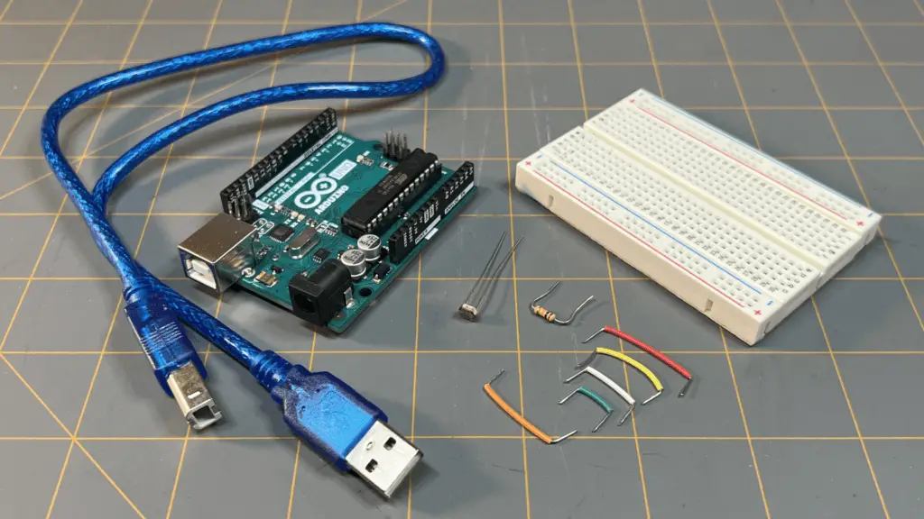
| Item | Quantity |
| Arduino Uno | 1 |
| Breadboard | 1 |
| Photoresistor (LDR) | 1 |
| 10kΩ resistor | 1 |
| Jumper wires | A variety of colors and sizes |
| USB cable | 1 |
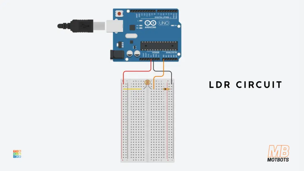
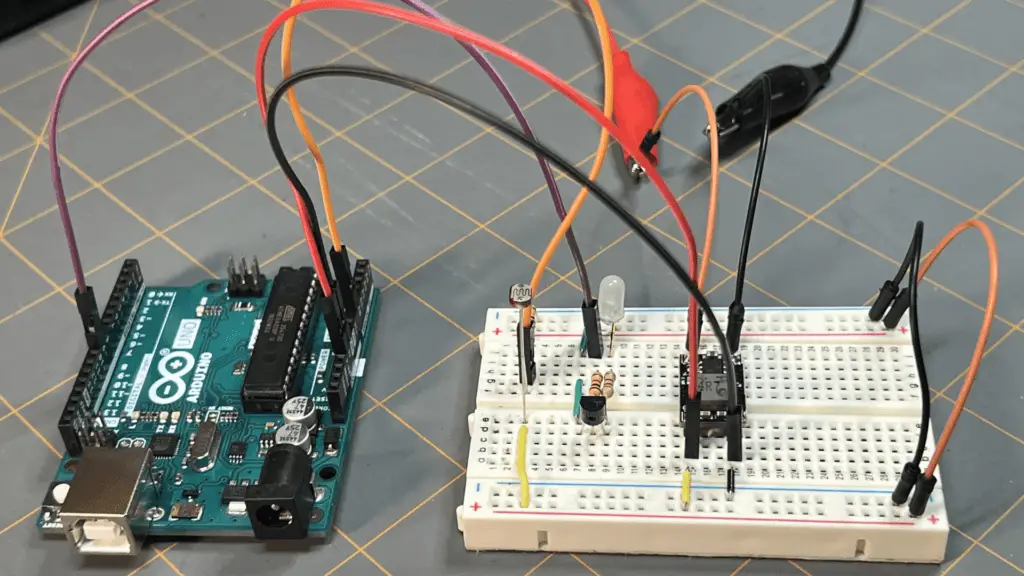
🔧 Building the Circuit
We’ll use a voltage divider to convert changes in light into a voltage the Arduino can read.
Wiring Steps:
- Connect one side of the LDR to 5V
- Connect the other side of the LDR to:
- A0 on the Arduino
- one side of the 10kΩ resistor
- Connect the other side of the resistor to GND
The LDR (light-dependent resistor) changes resistance based on light:
- Bright light → lower resistance
- Darkness → higher resistance
That change affects the voltage at the center point of the divider, which the Arduino reads using analogRead().
💻 Quick Test Code
Upload the following to your Arduino (Copy/Paste):
const int ldrPin = A0;                  // LDR leg tied to pin A0 on Arduino

void setup() {
  Serial.begin(9600);
}

void loop() {
  int lightValue = analogRead(ldrPin);  // read the analog value from pin A0
  Serial.println(lightValue);           // print the value on to the Serial Monitor
  delay(300);                           // delay 300 milliseconds — delay helps prevent overwhelming serial communication
}
Open the Serial Monitor and try:
- Covering the sensor with your hand or some other object
- Shining a light on it
- Moving it around your room or workbench area
You should see the values change in real-time on the Serial Monitor.

👀 What You Should Notice
You should notice that even though the light level seems steady, the readings might not be perfectly stable. They may:
- fluctuate slightly
- drift a bit
- respond differently depending on placement
This is completely normal—and it’s exactly what makes this circuit so useful for learning.
Just to reiterate, we’re going to build and explore this light-sensing circuit using a photoresistor (LDR) and the Arduino Uno.
As we progress with our discussions, we’ll focus more on this circuit we’re building together—going over each important topic as we progress through this section.
Don’t rush past this part—build the circuit, test it, and play with it.
The more you interact with it now, the more everything else in this section will make sense.
Driving Loads Safely
🚨 The First Rule: Don’t Power Everything from the Arduino
One of the most common beginner mistakes is trying to power real-world devices directly from an Arduino pin. It seems logical: “If I can turn a pin HIGH, why not power a motor or LED strip from it?”
Here’s why that’s a problem:
- Arduino I/O pins can supply ~20mA max (recommended)
- Voltage is limited to 5V
- Real devices often require higher current, higher voltage, and protection from electrical spikes
If you ignore this, you risk burning out a pin, damaging a microcontroller, and creating unstable circuits.
🙋♂️ I’ve done it all. My mission here is to try to teach you how not to make the same mistakes I have.
Here’s an image of a PIC microcontroller I fried a while back ago—you can just make out exactly where the source of smoke and the smell of burnt silicon had come from at the moment of its death ☠️.
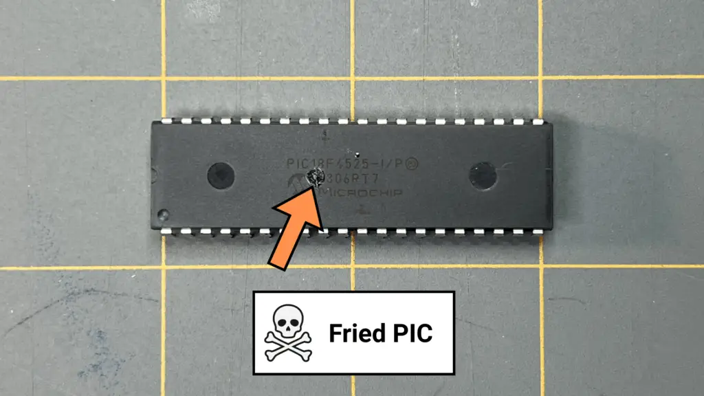
If it spins, clicks, or gets warm—it should NOT be powered directly from your Arduino.
🔌 The Solution: Use a Driver Stage
Instead of powering devices directly, the Arduino should act as a controller, not a power source. This is where a driver stage comes in.
Think of it like this:
- The Arduino gives the command.
- The driver handles the power.
Common Driver Options
- Transistor (BJT): Transistors are simple and cheap, and they are good for small loads. Transistors act like an electronic switch.
- MOSFET (Recommended): MOSFETs are more efficient than transistors. They are able to handle higher currents and are ideal for motors, fans, and LED strips.
- Relay: Relays electrically isolate circuits and can control high voltage (AC/DC), but they are mechanical and slower to respond.
Low-Side Switching
The most common approach to drive a circuit is via low-side switching. Low-side switching is where the load connects to the positive supply or +V.
For example, a MOSFET connects the load to ground and an Arduino controls the MOSFET’s gate. This keeps things simple and safe.

⚠️ Don’t Forget the Flyback Diode
If your load is inductive (like a motor or relay), it stores energy. When you turn it off, it releases that energy as a voltage spike. ⚡️ Without protection that spike can destroy your Arduino.
The solution? Add a flyback diode across the load.

⚡ Expanding Our Circuit: Adding a Driver Stage
Now that we can read light levels using our LDR circuit, the next step is to do something with that information.
Up to this point, the Arduino has only been observing the environment. Now, we’re going to make it act on what it sees.
We want our circuit to turn on a load (like an LED) based on light level. For example:
- Dark room → light turns ON
- Bright room → light turns OFF
This introduces a critical concept in embedded systems: A microcontroller doesn’t just measure—it makes decisions and controls outputs.
🚨 Why We Need a Driver Stage
At first, it might seem like we could just connect a device directly to an Arduino pin. But remember:
- Arduino pins can safely supply ~20mA
- Many real-world devices require much more current
If we try to drive a load directly, the pin may be damaged or the Arduino may behave unpredictably.
🔌 The Solution: A Transistor as a Switch
We’ll use a transistor as a driver stage. Think of it like this: The Arduino flips the switch and the transistor handles the power.
⚙️ Updated Circuit (Adding the Driver)
We’re going to add a simple NPN transistor driver to control an LED.
🧰 Additional Components
We’re going to add the following to our existing LDR circuit:
| Item | Quantity |
| NPN transistor (e.g., 2N2222) | 1 |
| 1kΩ resistor (base resistor) | 1 |
| LED | 1 |
| 220Ω resistor (LED current limiting) | 1 |

🔌 Wiring the Driver Stage
- LED + Resistor
- Arduino is not powering this directly
- Connect:
- LED anode → 5V
- LED cathode → collector of transistor through 220Ω resistor
- Transistor Connections
- Collector → LED (through resistor)
- Emitter → GND
- Control from Arduino
- Arduino digital pin (e.g., pin 9) → 1kΩ resistor → transistor base
💻 Arduino Code (Sensor → Decision → Output)
Now let’s connect everything together:
const int ldrPin = A0;                  // LDR leg tied to pin A0 on Arduino
const int ledControlPin = 9;
const int threshold = 400;

void setup() {
  pinMode(ledControlPin, OUTPUT);       // set pin 9 as OUTPUT
  Serial.begin(9600);
}

void loop() {
  int lightValue = analogRead(ldrPin);  // read the analog value from pin A0
  Serial.println(lightValue);           // print the value on to the Serial Monitor

  if(lightValue > threshold) {          // if lightValue greater than threshold
    digitalWrite(ledControlPin, LOW);   // turn LED off
  } else {
    digitalWrite(ledControlPin, HIGH);  // turn LED on
  }

  delay(300);                           // delay 300 milliseconds – delay helps prevent overwhelming serial communication
}
For the threshold value, I chose 400. The highest value I observed when watching the Serial Monitor for the printout of the lightValue was in the 460s or so, when the LDR was in its darkest conditions during testing. You can choose whatever threshold value you like—higher or lower.
With the threshold value set to 400, the code says to turn the LED off when the lightValue exceeds the threshold (when it’s bright conditions), and to turn the LED on when the lightValue is less than the threshold (when it’s dark conditions).
You can switch the digitalWrite values around (HIGH, LOW) to make the LED turn on in light and off in darkness—whatever you prefer.
🧠 What’s Happening
Arduino outputs HIGH, so a small current flows into the transistor base. The transistor then turns ON, completing the path to ground. Current flows through the LED and then it turns ON.
When the Arduino outputs LOW, the transistor turns OFF, therefore the LED is OFF.
🔍 What to Try
Now interact with your circuit:
- Cover the LDR → LED should turn ON
- Shine light → LED should turn OFF
- Adjust the threshold value to fine-tune behavior
This small upgrade demonstrates something very important:
- The Arduino is not powering the LED directly
- It is controlling a switch (the transistor)
- The transistor safely handles the currents
This is the same idea used when controlling motors, fans, relays, and LED strips.
If your Arduino is controlling something bigger than a single small LED, you should be thinking about a driver stage.
🔋 Powering the Arduino from 12V Systems
🌍 The Real World Runs on More Than 5V
In real applications—robots, vehicles, shop systems—you’re often working with 12V batteries, 24V systems, or power supplies.
So, if we’re intending to use an Arduino for a “real world” project or use for something we need, how do we safely power it?
🔌 Arduino Uno Power Options
The Arduino Uno provides a few ways to power it:
- USB (5V) – development and testing
- Barrel Jack (7-12V recommended)
- VIN Pin (7-12V input)
- 5V Pin (regulated input – advanced use only)
Although there are several different options to power an Arduino, there are different scenarios of which option to choose to do so, as well as a recommended way, such as with using the barrel jack port of the Arduino Uno.
🔥 The Hidden Danger: Heat
If you feed 12V into VIN or the barrel jack, the onboard regulator must drop it to 5V. That means the extra voltage becomes heat. For example:
- Input: 12V
- Output: 5V
That’s a 7V drop of heat buildup! Too much current can lead to overheating.
The Better Solution: Buck Converters
A DC-DC buck converter steps voltage down efficiently.
Instead of burning off energy as heat, it converts it.
The benefits of a DC-DC buck converter are that they have a higher efficiency, produce less heat, and are more reliable.
Let’s say that you’re building a system powered by a 12V battery:
- Use a buck converter to step down the voltage to 5V
- Feed that into the Arduino’s 5V pin
- Power sensors and modules from the same regulated line
Voltage is like pressure—without control, it will break things fast.
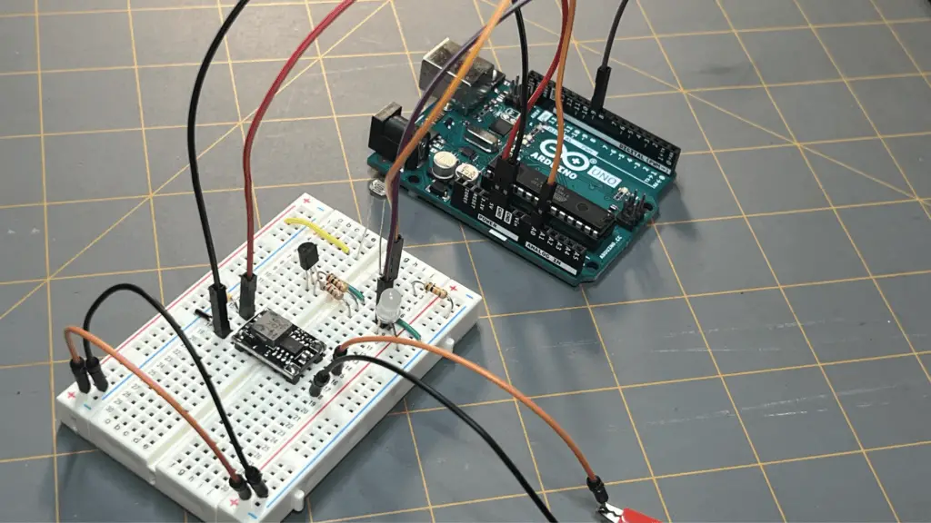
⚡ Expanding Our Circuit: Powering the Arduino with 12V
Up to this point, our circuit has been powered through the Arduino’s USB connection. This is fine for development, but real-world systems don’t usually run from a computer. Instead, they often use:
- 12V batteries
- power supplies
- vehicle electrical systems
We want to power our entire system using a 12V source, while still safely running the Arduino Uno, the LDR sensor circuit, and the driver stage.
So let’s take our light sensing circuit and step into the real world.
⚠️ Can we just use VIN?
The Arduino Uno provides a VIN pin and a barrel jack for higher voltage input. Technically, yes—you can connect 12V here.
But there’s are a couple important details:
- The Arduino uses a linear regulator to drop that voltage down to 5V.
- That voltage drop turns into heat inside the regulator.
- If your circuit starts drawing more current, that heat can build up quickly—this can lead to unstable operation, overheating, and reduced reliability.
The way we’ll approach powering our Arduino is by using a DC-DC buck converter. Doing so will efficiently step 12V down to 5V. Instead of burning off energy as heat, it’ll convert it.
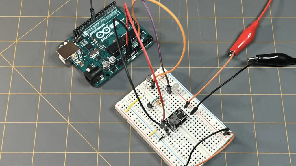
🧰 What You’ll Add
To upgrade your circuit, you’ll need:
- 12V power source (battery or supply—I’m using a bench power supply)
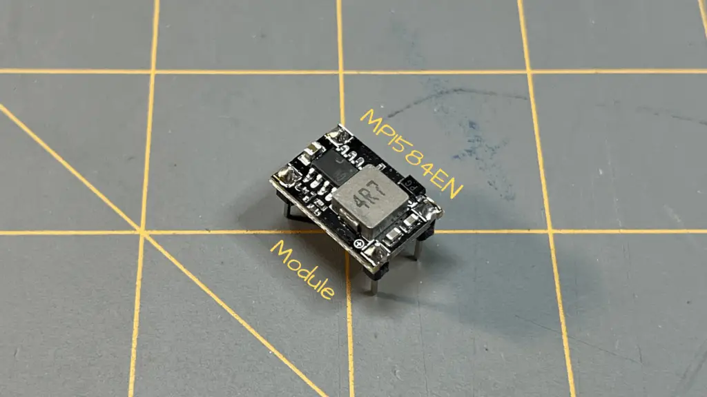
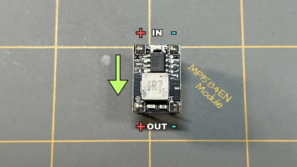
- DC-DC buck converter (e.g., LM2596 module—I’m using a MP1584EN module board)
If you’re using a MP1584EN module board like I am, you may need to solder some pins to the four corners of the board. The following video clip shows this process:
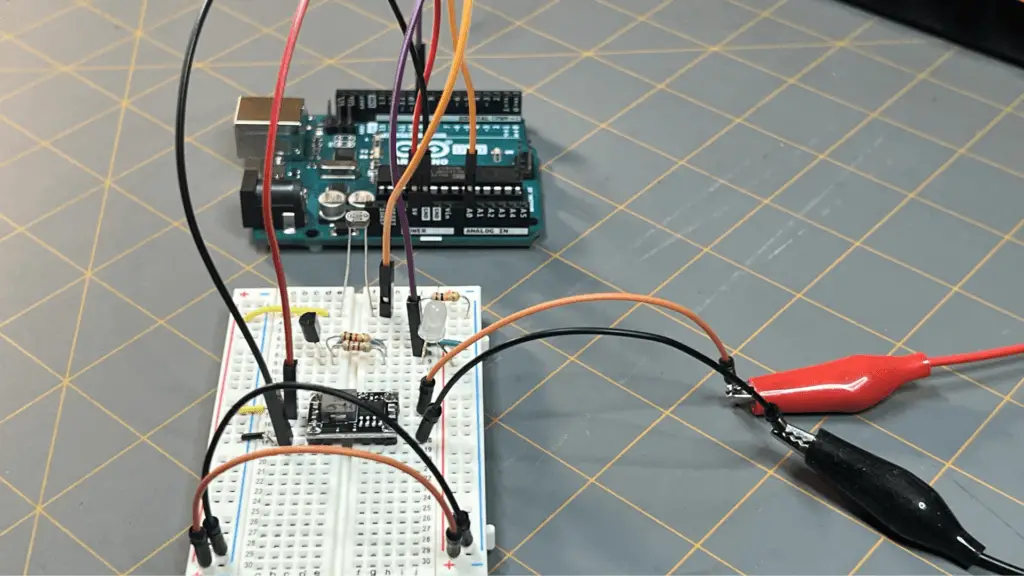
🔌 Updated Power Wiring
- Connect 12V power source to the input of the buck converter
- +12V → IN+
- GND → IN−
- Adjust the converter output to 5V, if needed (very important). Since I’m using a MP1584EN module board, it uses a MOSFET onboard that automatically provides an output of 5V.
- Connect the buck converter output:
- OUT+ → Arduino 5V pin
- OUT− → Arduino GND
- Keep your existing circuit connections:
- LDR divider still uses 5V and GND
- Transistor driver still shares the same ground
Now the entire system is powered from our 12V source. The buck converter creates a stable 5V rail and the Arduino and circuit run from that regulated supply.
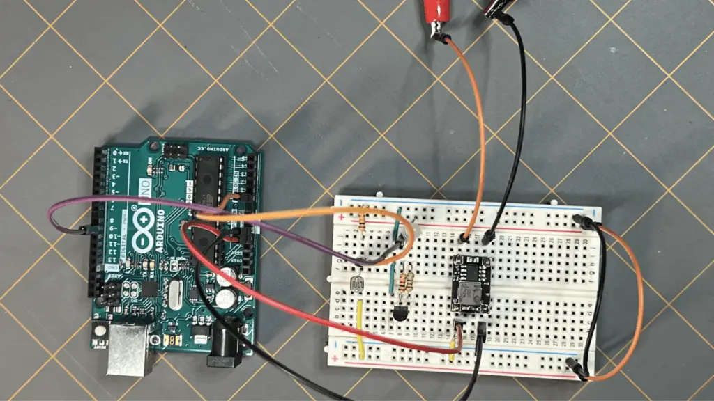
🌎 The Critical Detail: Common Ground
Even with a 12V system, one rule still applies: Everything must share a common ground!
That includes:
- 12V supply
- buck converter
- Arduino
- LDR circuit
- transistor driver
Without a shared ground: signals won’t behave correctly, reading may become unstable, and outputs may not respond as expected.
Let’s get into what grounding and noise in a circuit is, next.
Grounding & Electrical Noise
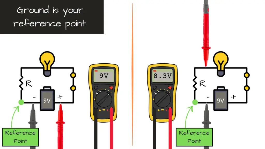
🤔 What Is “Ground” Really?
In electronics, ground is your reference point. All voltages are measured relative to ground.
The key concept is that all parts of your system must agree on what “ground” is.
The Importance of Common Ground
If you’re using an Arduino, external power supply, sensors, and a motor they must share a common ground. Without it signals become meaningless and behavior becomes unpredictable.
⚠️ Real-World Problem: Electrical Noise
When you introduce motors, relays, and switching devices, you introduce:
- Voltage spikes
- Electrical interference
- Unstable readings
The symptoms could be:
- Random resets
- Flickering outputs
- Noisy sensor data
Common sources of noise:
- DC motors
- Relays
- Switching regulators
- Long wires
Practical fixes:
- Star Grounding: This is where you connect all grounds to a central point. Doing so reduces interference paths.
- Separate Power Paths: You can keep motor power separate from logic power. Connect grounds, but not power rails.
- Decoupling Capacitors: Place capacitors near microcontroller power pins. This will help smooth voltage fluctuations.
In the previous section of this series, we made a simple circuit using a PIC18F4525 microcontroller where we added a decoupling capacitor across the main 5V and GND rails of the breadboard.
The OwlBot Project Series shows an excellent demonstration on grounding an Arduino circuit that contains a DC motor, solenoids, a PIR sensor, MP3 player, and LEDs. Throughout that series we went over exactly everything we’re discussing here:
- Powering an Arduino Uno
- Driving a DC motor and solenoids with MOSFETs
- Proper grounding techniques
- and MUCH MORE!
Reading the OwlBot series and trying the project out for yourself could help out your understanding of circuit design and building, as well as using an Arduino microcontroller for your next project idea. I highly recommend that you go check The OwlBot Project Series out for yourself!

Most “weird bugs” in electronics can often be attributed to grounding issues.
📡 Filtering Sensor Readings
In theory, sensors give clean values, but in reality values fluctuate. Signals often contain noise and readings can jump around. This is due to electrical interference, mechanical variation, and ADC resolution limits.
🔧 Hardware Filtering
A way to alleviate fluctuations and noise is to add RC filters and pull-up/pull-down resistors to your circuit.
Capacitors (RC Filter)
- Smooth rapid changes or do not allow rapid changes in voltage
- Reduce noise
Pull-Up / Pull-Down Resistors
- Stabilize floating inputs

💻 Software Filtering
Sometimes hardware isn’t enough—or you want flexibility. You can also alleviate fluctuations and noise by doing some simple changes in code.
Averaging (Simple and Effective)
As an example concept, you could take multiple readings—say from a sensor—then, average them out and use the result.
🧪 Example: Arduino Averaging Code
The following code is an example of averaging sample readings from a sensor pin. This code is not part of the example LDR circuit we did earlier.
int sensorPin = A0;
int numSamples = 10;

int readSmoothedValue() {
  int total = 0;

  for (int i = 0; i < numSamples; i++) {
    total += analogRead(sensorPin);
    delay(5);
  }

  return total / numSamples;
}⚙️ When to Use What
| Situation | Solution |
| Fast noise spikes | Capacitor |
| Floating input | Pull resistor |
| Minor fluctuations | Averaging |
| High precision needed | Combine both |
Raw sensor data is messy—your job is to turn it into something useful.
Video: LDR Circuit – Embedded Intelligence Series: Section 3

Bringing It All Together
Let’s combine everything into a real-world system. An example system could be:
- Arduino reads a temperature sensor
- Sensor readings are filtered
- Arduino controls a fan via MOSFET
- System powered from a 12V battery
- All components share a common grounding
You may remember a similar project we built earlier—the 555 Temperature-Controlled Fan Controller. In that circuit, a thermistor detected changes in temperature and sent a signal to activate a fan once a certain threshold was reached. That’s the moment it stopped being just a circuit—and started becoming a complete embedded system.
🚀 What This Means for You
At this point, you’ve crossed an important line. You now understand:
- How to safely control real-world devices
- How to power microcontrollers in practical systems
- Why grounding matters
- How to clean up noisy signals
You’re no longer just experimenting—you’re engineering!

Up Next in the Embedded Intelligence Series
Now that you understand how to safely interface a microcontroller with the real world, it’s time to take the next step—making your systems smarter.
🧠 Section 4 – Smart Behavior
We’ll move beyond simple control and start introducing intelligence into our systems, including:
- Hysteresis implemented in software
- Calibration techniques and thermistor math
- State machines for makers
- Data logging and basic telemetry
- An introduction to closed-loop control
This is where your projects begin to think instead of just react.
⚙️ Section 5 – Next Steps
From there, we’ll expand our systems with practical, real-world upgrades:
- Adding a display for feedback
- User-adjustable thresholds
- Alarm and alert modes
- Designing a proper 12V version done right
🔧 Sections 6 & 7 – Bringing It All Together
Finally, we’ll bring everything full circle by rebuilding earlier projects—this time with embedded intelligence:
- 🔴 Arduino-Controlled LED Blinker
- 🌡️ PIC Temperature-Controlled Fan Controller
These aren’t just repeats—they’re evolved systems, building on the original circuits and transforming them into fully programmable, intelligent designs.
What started as simple component-based circuits will becoming something far more powerful—
adaptive, intelligent systems built around microcontrollers.
😎 We’re just getting started.