0:00
okay this video is going to be a
0:01
supplemental video on the blog post on
0:06
the website on mosfets entitled
0:09
understanding mosfets key Concepts and
0:11
practical examples I'll leave a link
0:14
down in the description below to that
0:16
reading material if you're interested
0:18
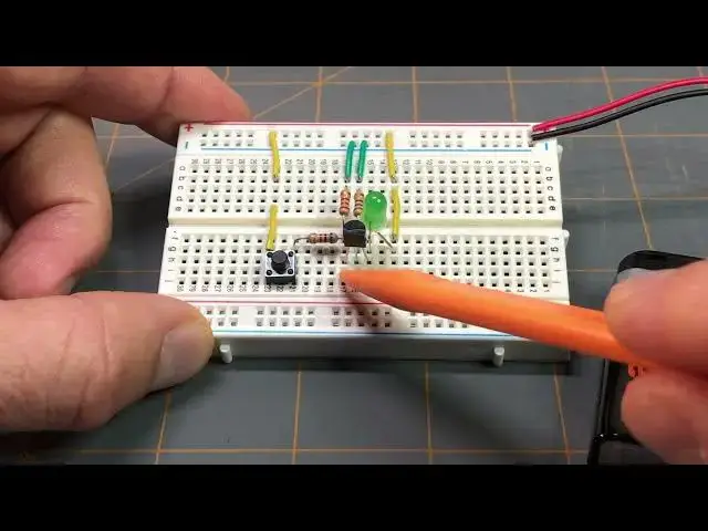
what I have you zoomed in on here uh as
0:21
you can see it's a breadboard uh with a
0:24
circuit on it and it's the same circuit
0:28
setup that you can see here
0:35
and that circuit like I said is the
0:36
exact same circuit uh on the example
0:39
switch application for this particular
0:42
mosfet that we did on that post again
0:45
I'll leave the link down in the
0:47
description below and it also has the
0:49
schematic that you can find there as
0:51
well if I tilt this up we can just
0:55
briefly go over that setup here
1:00
I have a 9volt battery supply here and
1:03
its terminals go to the power rail here
1:06
of the breadboard we have the positive
1:08
Supply with the red wire and the
1:09
negative Supply with the black wire if
1:12
we follow down the positive Supply we
1:14
reach this yellow jumper wire which is
1:16
in line with this yellow jumper wire
1:19
which is in line with the anode lead of
1:22
the green LED and then the cathode lead
1:25
of the green LED goes to the drain of
1:30
mosfet if we look at the center lead of
1:33
the mosfet that is the gate and in line
1:36
with the gate if I tilt up here and try
1:39
to move some of this stuff around so we
1:41
can see better we can see that there's
1:45
this resistor here it's lead is in line
1:49
with the gate and then we have this
1:52
resistor here which is in line with this
1:57
green jumper wire which goes to the Nega
2:00
Supply uh or the negative power supply
2:04
this is the 500 Ohm resistor that we
2:09
example this happens to be a 560 Ohm
2:12
resistor because I don't have a 500 Ohm
2:14
resistor so I'm using a 560 Ohm resistor
2:18
for this setup here just for
2:20
demonstration purposes but in the
2:23
calculations we did we calculated for a
2:26
500 Ohm resistor and that's for this one
2:32
schematic right here is this other
2:34
resistor this is considered resistor R1
2:38
in the schematic and this is the 1K Ohm
2:40
resistor and it's again both of these
2:44
resistors are in line with the gate lead
2:49
mosfet looking back at the 1K Ohm
2:52
resistor it's other lead is in line with
2:55
this push button switch and the other
2:59
lead of this push button switch is in
3:02
line with this yellow jumper wire which
3:04
is in line with this yellow jumper wire
3:07
which is attached to the positive rail
3:11
of the positive Supply looking back
3:14
towards the uh Source lead of the mosfet
3:19
in line with that lead is this other
3:22
resistor and this is the 200 Ohm
3:26
resistor and this is considered resistor
3:29
R3 in the schematic and it's in line
3:33
with this green jumper wire which goes
3:41
so again this was for the switch
3:45
application uh example in the blog post
3:48
and if I were to press the button here
3:51
we'll see that the green LED lights
3:56
up you can see it lit up right there and
3:59
this is all controlled thanks to
4:03
this in Channel enhancement mode mosfit
4:07
again enhancement mode means that it's
4:09
normally off so if I'm not pressing the
4:12
button the LED is off and nothing's
4:14
happening if I press the button the LED
4:17
comes on all that's explained in that uh
4:21
blog post again that I mentioned that I
4:24
going to leave that link down in the
4:26
description below but you can follow
4:28
along on that reading material and set
4:32
up your own uh circuit just like this
4:34
one for the switch application using the
4:39
mosfet uh Before I Let You Go I also
4:41
wanted to go over like we
4:46
did in that example where we used a
4:50
multimeter to take a reading across
4:54
resistor R1 the 1K resistor and we read
4:57
a voltage of 6 volts I just wanted to
5:00
demonstrate that real quick so I will
5:06
out again if you haven't read that blog
5:10
post this might not make a lot of sense
5:13
right now so I encourage you to check
5:20
along with this example circuit and
5:24
everything would become much clearer to
5:27
that so like I said I'm just just going
5:31
to uh do exactly like we did in that
5:36
example circuit where we wanted to make
5:38
a reading across that 1K Ohm
5:42
resistor resistor R1 in the circuit and
5:47
example in theory we were to get 6 volts
5:52
now I probably won't get the exact
5:54
voltage reading here but it should be
5:57
fairly close and I'm going to use this
6:01
a makeshift finger here because I don't
6:02
want to get my hand in the way and I'm
6:04
going to press down we see the LED light
6:06
up and we are getting a reading of about
6:17
volts again I'm not going to get an
6:19
exact reading as we did in the example
6:22
the example gave a reading of six volts
6:26
demonstrate that part of the example in
6:30
post uh where we needed to figure out uh
6:41
R2 and that's this resistor here and we
6:45
calculated it to be 500 ohms again
6:49
excuse me it's this other resistor over
6:51
here uh again we calculated it to be 500
6:55
ohms and I ended up having to use a 560
6:59
oh resistor because I don't have a 500
7:02
resistor but I just wanted to show you
7:06
that real quick and kind of go over the
7:08
the circuit here and share that with you
7:11
so I hope that you go check
7:17
post understanding mosfets key Concepts
7:21
examples I'll leave all that information
7:24
that you need for that down in the
7:27
description below and I'll leave you
7:33
of pressing the button and watching the