Up next in 10

Understanding MOSFETs: MOSFET as a Switch (UPDATED Supplemental Video)
Feb 2, 2025

This is a supplemental video for the blog post at motbots.com titled "Understanding MOSFETs: Key Concepts and Practical Examples".
_______ THIS IS AN UPDATED VIDEO _______
This is an updated video from the previous video titled "Understanding MOSFETs: MOSFET as a Switch (Supplemental Video)" here:
➡️ https://youtu.be/DVFMZ24-mMQ
That video was updated here for a mistake that was made on the associated blog post for the video. Someone in the comments from that video brought it to my attention and was kind enough to let me know about it, as well as share some of his knowledge of the topic, which was greatly appreciated! Thank you so much @RexxSchneider for your help in finding my mistake and letting me know about it! It really helped me and all who watches. You're so cool and greatly appreciated! 😎👍
___________________________________________
In this video we go over (in more detail than the previous video) each component that has been set up on the breadboard. The website explains a problem in detail on a circuit similar to this one. If you're interested in learning more, please visit the website using the link for that example and for the subject matter on MOSFETs below:
📋 PARTS LIST:
➡️ https://motbots.com/understanding-mosfets/#Parts_List_to_Create_MOSFET_Switch_Circuit
📃 SCHEMATIC:
➡️ https://motbots.com/understanding-mosfets/#Schematic_for_MOSFET_Switch_Application
Video for Our Website Page: "Understanding MOSFETs: Key Concepts and Practical Examples"
Show More Show Less View Video Transcript
0:00
okay this is a video meant to be a
0:02
supplemental video for our blog post on
0:05
the topic of mosfets located on the
0:08
mbots website titled understanding
0:11
mosfets key Concepts and practical
0:15
examples I'll leave a link in the
0:17
description below to that reading
0:19
material if you're interested in this
0:21
particular
0:23
topic I've actually already created this
0:26
video once and posted it but thanks to a
0:29
very formative comment made by Rex
0:32
Schneider I was informed of a mistake
0:35
I'd made on the original circuit that I
0:38
created for this blog post I ended up
0:41
having to correct that mistake which
0:43
changed some of the component values for
0:46
this particular circuit here as well as
0:49
the uh
0:50
calculations which is why I'm creating
0:53
the second video here but all should be
0:56
in order now and all has been promptly
0:58
corrected on the site at least I hope
1:01
that it is I tend to make quite a lot of
1:05
mistakes especially with stuff like this
1:07
so we can only cross our fingers here so
1:10
it's it's always a learning experience
1:12
which I always appreciate that by the
1:15
way that mistake video is still up I
1:18
didn't take it down so if you're
1:20
interested in seeing it uh I don't know
1:22
why you would be interested in seeing it
1:25
I mean there's still some valuable
1:26
information in there I guess but it's
1:29
pretty much the same video that this
1:30
one's going to be but with the obvious
1:33
Corrections here so uh you can choose to
1:36
do so if you'd like to I'll I'll leave
1:38
the link to that video here uh too down
1:42
in the description
1:43
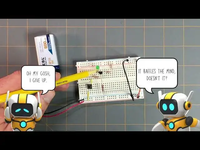
below anyway what we have here in front
1:46
of us now is a breadboard with our our
1:48
mosfet circuit and it's already uh all
1:51
connected up here this is the exact same
1:54
circuit setup that you can see here
2:01
and that circuit like I said is the
2:03
exact same circuit on the example switch
2:05
application for this particular mosfet
2:09
that we did on that post again I'll
2:11
leave the link down in the description
2:13
below which is where you can also find
2:16
the schematic for this setup as well so
2:19
if I zoom you in here a little bit and
2:21
I'll reposition
2:24
this maybe if I move this sheet of paper
2:27
out of the way real quick we'll be
2:28
needing that later just not right
2:33
now let me zoom in a little bit now that
2:37
we're zoomed in I can kind of briefly go
2:40
over the setup here so I tried to set
2:43
this up on the breadboard uh almost
2:46
exactly like it was uh in the schematic
2:49
that is on the website that's provided
2:52
on the website I know you can't see that
2:55
uh in the camera right now
2:58
but here I have
3:00
uh my battery source it's a 9vt battery
3:04
and the two terminals coming off that
3:07
battery the red terminal is the positive
3:09
Supply and the black uh lead or terminal
3:13
is the the negative Supply and if we
3:16
follow that red wire the positive Supply
3:19
it goes to the positive Supply rail or
3:23
power rail of the breadboard here and
3:26
then I've also continued that Supply
3:29
with using this orange jumper wire here
3:33
and continued it over to the other
3:36
positive power rail on this on this
3:41
breadboard and again going back to that
3:45
positive uh lead of the battery it goes
3:48
to the positive power rail to this
3:50
yellow jumper wire that goes to a lead
3:53
on this push button switch a normally
3:56
open push button switch on this end and
3:59
then the other turn terminal on the
4:00
other side of that push button switch is
4:03
in line with this yellow jumper wire
4:06
which is in line to the lead of this
4:09
resistor here this is resistor R1 in the
4:15
schematic again you can find that
4:17
schematic uh on the website I'll leave
4:20
the link to that down in the description
4:22
below this is the onek ohm resistor
4:25
resistor
4:26
R1 and the other lead of that resistor
4:29
is in line with the Gate of this uh 2in
4:35
7000 mosfet and the gate lead is the
4:38
center lead I know you can't see it from
4:40
The View that you're at but the lead to
4:43
this 1K Ohm resistor goes to the center
4:46
lead of this mosfet and that is the
4:49
gate also in line with the
4:53
gate is the lead of this resistor here
4:58
and this resistor represents resistor R2
5:01
from that example circuit in the
5:05
schematic this is the 2km resistor that
5:08
we find the value for in that example
5:12
switch
5:13
application and then the other lead of
5:16
this 2K Ohm resistor goes to the
5:19
negative Supply or negative rail of the
5:22
breadboard here and I forgot to mention
5:24
that the negative rail uh on this end of
5:29
the radbard is also connected with this
5:32
black jumper wire and it goes to the
5:34
other uh negative power rail on this
5:38
side of the breadboard so looking back
5:42
at the mosfet again if we look at its
5:46
drain pin which is uh from your view
5:51
above the circuit here it's this right
5:53
side pin and it's in line with this
5:57
resistor here these two two resistors
6:00
are in series and they're representing
6:03
my 200 Ohm resistor which is resistor R3
6:07
in the schematic these are two 100 ohm
6:10
resistors that when set in series add up
6:13
to 200 uh ohm or 200
6:17
ohms so that drain lead of the mosfet is
6:22
in line with this lead of this 100 ohm
6:26
resistor which is in line with this 100
6:29
ohm res resistor making two making up
6:31
200
6:32
ohms together and the end of this
6:36
resistor is in a point on the negative
6:41
Supply rail of the
6:44
breadboard looking back at the mosfet on
6:48
its source pin which is this left pin
6:52
from your view above here I know you
6:55
can't see the pin but it's on the left
6:58
side uh as the mosfet is currently
7:01
oriented and that Source pin is in line
7:05
with the anode or excuse me the cathode
7:10
of the LED and then the anode lead of
7:13
the LED goes to the positive power rail
7:18
on this side of the
7:22
breadboard and here in a little bit I'll
7:24
I'll give you a more close-up view so
7:26
you can see uh how everything's hooked
7:29
up and the placement of everything as it
7:33
is uh right now I know that it's a
7:36
little difficult to see how things line
7:39
up from a top view but again I I'll I'll
7:43
give you a different View later on in
7:45
this video so again this this was for
7:48
the switch application example in the
7:50
blog post and if I were to press the
7:54
button here we could see that the green
7:56
LED lights up
8:00
and this is all controlled thanks to
8:02
this in Channel enhancement mode
8:06
mosfet and again an enhancement mode
8:09
means that it's normally off so as you
8:12
can see here if I'm not pressing the
8:14
button the LED is currently off and
8:17
nothing's happening if I press the
8:20
button the LED comes
8:24
on and all that is explained in in that
8:27
blog post that I mentioned and again
8:29
I'll leave all that in the description
8:32
below but you can follow along in that
8:35
reading material and set up your own
8:37
circuit just like this one for the
8:39
switch application using the 2n7000
8:42
moset in that example we're given some
8:46
values of the circuit and we're asked to
8:48
find some unknown values uh in that in
8:52
this case we're asked to find the
8:56
resistor value of R2
8:59
which is this resistor right here this
9:02
is the 2K Ohm resistor and that's the
9:04
value that we found uh in that example
9:07
problem and we're also asked to find the
9:12
uh drain to Source voltage if you
9:14
haven't read that blog post all this may
9:17
not make a lot of sense right now so I
9:19
encourage you to go check out that link
9:21
and follow along with this example
9:23
circuit here everything would be much
9:26
more clearer if you did I just wanted to
9:28
show you this completed circuit the
9:31
working circuit here uh real quick and
9:34
kind of go over the circuit and share it
9:36
with you but before I let you go I just
9:39
wanted to go over something so I'm going
9:41
to move this out of the way and I'm
9:45
going to zoom you back
9:47
out and I want to bring back this
9:51
schematic here maybe I'll Zoom you in
9:53
just a little bit
9:56
more so in the example schematic or the
10:00
example problem on the blog
10:02
post were given values like the 9vt
10:05
power
10:06
supply uh we're given that we're going
10:10
to be using a drain current value of 20
10:15
milliamps we're given that the voltage
10:18
drop across the LED in the circuit is 3
10:21
volts and we're given values like uh the
10:25
resistor value for R3 of 200 ohms the
10:29
resist resistor value of R1 which is 1K
10:32
ohm and like I said we're asked to find
10:36
uh the value of
10:37
R2 and the value of the drain to Source
10:40
voltage now these values are already in
10:43
place here this is just to help me out
10:46
uh in discussing this example problem
10:48
but based on the values given what we
10:51
were able to do is uh to figure out the
10:55
voltage uh drop across resistor R3 since
10:59
we know the value of the 200 Ohm
11:02
resistor and we know the value of the
11:04
drain current of 20
11:07
milliamps looking at the circuit we
11:09
would know that uh the drain current
11:12
going into the drain of the
11:14
mosfet would be the same uh value uh of
11:18
the current coming out of the source of
11:20
the moset hence the source value is
11:23
equal to the drain value which is equal
11:25
to the 20 milliamps so in knowing
11:30
that the source current is 20
11:32
milliamps and the value of resistor R3
11:36
is 200 ohms then we can use ohms law to
11:40
find the value of the voltage drop
11:43
across R3 so if we were to multiply the
11:47
20 milliamps times the 200 ohms we would
11:50
get a value of 4 volts or that would be
11:53
the voltage drop across resistor R3 and
11:57
in that example problem on the Block log
11:59
post we were given that the gate Source
12:01
voltage is 2 volts so on knowing that
12:04
the gate Source voltage is 2 volts and
12:07
then us figuring out that the voltage
12:10
drop across R3 is 4 volts the sum of
12:14
these two voltages is 6 volts because
12:18
this we could take the sum of the two
12:20
voltages because they're in series here
12:23
so that means that the voltage potential
12:26
across these two points between the gate
12:28
and the negative Supply or ground of the
12:32
circuit you can see that all of the
12:35
negatives go to this node of the circuit
12:40
that we can say that these two points
12:43
between the gate and the S and the
12:45
negative Supply and these two points
12:49
across resistor R2 the voltage drops or
12:52
the voltage potentials should be equal
12:56
so that's why or how we got the value 6
12:59
volts across R2 because 2 Vols plus 4
13:02
volts is 6 volts that's the voltage
13:05
potential voltage potential between
13:07
these two
13:09
points which should be the same voltage
13:12
potential across these two points
13:14
because they're in parallel and voltage
13:17
Potentials in parallel with each other
13:20
are equal to each other so 6 volts
13:22
across these two points 6 volts across
13:24
these two points so now in knowing that
13:26
the voltage drop across R2 is six PS we
13:30
can't quite figure out what the value of
13:33
R2 is because we don't know the value of
13:37
R2 that's what we're trying to figure
13:39
out and also we don't know what the
13:42
value of I is through R2 but since we do
13:46
know the voltage across R2 and we know
13:48
the
13:49
voltage value of the source for
13:52
V1 then the voltage drops across
13:56
R1 and across R2 since this circuit here
14:01
is considered a series circuit this Loop
14:03
here the sum of these two voltage drops
14:06
should
14:07
equal to the source voltage of V1 now
14:11
even though it's the voltage drop across
14:14
R1 is given here in this print off we
14:17
didn't originally know what this value
14:19
was so in order to find out what the the
14:23
voltage drop was across R1 the sum of
14:27
whatever this voltage drop is plus this
14:30
plus this voltage drop should equal to 9
14:32
volts so if I have six volts here this
14:35
must be 3 volts across R1 because 6
14:38
volts + 3 volts is 9 volts which is
14:40
equal to the voltage value of the source
14:45
voltage of B1 so now that we knew what
14:50
the voltage drop across R1 is then we
14:53
can figure out what the value of the
14:55
current is coming from our source volt
14:59
voltage going through uh resistor R1
15:03
again we'd use ohms law for that since
15:06
we're given the value of R1 to be 1K ohm
15:10
we divide the 3 volts across R1 by 1 K
15:15
ohm and that would give us a current
15:18
value I of 3 milliamps and like I said
15:22
this Loop of the circuit is in series
15:26
because that current value is not going
15:29
going through the gate because uh a gate
15:33
of a mosfet acts as a capacitor so
15:36
there's uh we can just say ideally that
15:40
there's no current going through the
15:42
gate therefore the current is going
15:44
through this section of the circuit here
15:47
and this is a series
15:49
circuit so if this is a series circuit
15:52
whatever current is going through
15:54
resistor R1 is also the same current
15:57
going through resistor R2 and and that
15:59
is just the current I which we just
16:02
found to be 3 milliamps so now that we
16:04
know the value of I and we know the
16:07
value of the voltage drop across R2 we
16:10
can again use ohms law to find what the
16:12
value of R2 is and that's just the 6
16:16
volts divided by the 3 milliamps which
16:20
gives
16:20
us a resistor value of 2,000 ohms or 2
16:25
kiloohms although I didn't I didn't put
16:28
that back value in here but that's the
16:30
value of the resistor R2 that we were
16:33
able to figure out in that example
16:35
problem and then again we were asked to
16:37
find what the drain to Source voltage uh
16:41
was across the mosfet so all we would
16:45
need to do there is again use Kiros
16:47
voltage law since we know what the value
16:50
of the source voltage is here it's 9
16:54
volts we were given that the voltage
16:56
drop across the diode or the LED was 3
17:00
volts and we found that the voltage drop
17:02
across resistor R3 was 4 volts this
17:06
portion of the circuit is a series
17:08
circuit so the voltage drops across
17:12
these components of the circuit should
17:14
equal to the source voltage of the V2 so
17:19
3 + 4 is
17:22
7 so that means that the value or the
17:25
voltage drop across uh the drain and
17:28
source of the mosfet should be 2 volts
17:31
because 4 + 3 is 7 + 2 is 9 Vols which
17:36
is equal to the 9 volts uh the source
17:39
voltage for v2 so I just wanted to kind
17:42
of go through that real quick uh this
17:44
being from the exact same problem from
17:48
the blog post this is based on ideal
17:51
conditions and I thought it'd be neat to
17:54
go over the real world conditions
17:58
of our real
18:01
world uh circuit that we have here so
18:05
what I did is I took my
18:09
multimeter and I took the probes and
18:13
what I first did before hooking the
18:14
battery up to the breadboard is I took
18:18
my probes and I
18:21
measured the voltage across the battery
18:24
terminals and that gave me the source
18:27
voltage of 8.1 5 volts I'm obviously
18:30
using one battery here although it shows
18:32
two batteries in the circuit I'm using
18:35
one for the my circuit here on the
18:38
breadboard so in that case V1 and V2 is
18:43
8.15 volts which is the reading I got uh
18:47
from my multimeter reading and then what
18:50
I what I proceeded to do is before I put
18:53
the resistors into the breadboard is I
18:56
took my probes and and placed my
19:00
multimeter into uh its resistance uh
19:05
reading mode and I took uh resistor
19:09
reading values across each one of the
19:11
resistors out of the circuit and
19:15
uh for my 1K Ohm resistor resistor R1 I
19:20
ended up getting a reading of 979 ohms I
19:24
took a reading and that was this
19:26
resistor here the 1K ohm resistor I took
19:29
a reading of resistor R2 and got a
19:33
reading of
19:35
1,955 ohms even though it's labeled as a
19:38
2K Ohm resistor and then again I'm using
19:42
two 100 ohm resistors to make up for the
19:45
200 Ohm resistor value of
19:47
R3 and I took measurements across each
19:50
one of these resistors one being 88.3
19:54
ohms another reading for the other
19:57
resistor being 87. 9 ohms and the sum of
20:01
those two uh values gave me a value of
20:06
1762 ohms and not 200 ohms so those are
20:11
the real real world values of uh
20:14
resistor R1 R2 and
20:17
R3 and then with everything hooked up in
20:20
my circuit and the button pressed I took
20:25
voltage readings
20:26
across the L L and for the LED I'm using
20:31
I got a voltage drop of 2.05 volts I
20:35
took a voltage reading across the drain
20:37
and source of the mosfet and the voltage
20:40
reading I got from the multimeter was
20:43
2.51 volts and then I took a voltage
20:46
reading across resistor R3 which is
20:49
across these two uh 100 ohm resistors
20:53
here and I got a voltage reading of 3.45
20:57
volts so again again Kirk off's voltage
21:00
law says that the sum of the voltage
21:03
drops in this case across the diode
21:07
across or across the LED and across the
21:11
drain and source of the mosfet and
21:13
across resistor R3 those voltage drops
21:16
the sum of them should equal to my uh
21:21
Source
21:22
voltage which is 8.15 volts and if I
21:27
were to add to 2.05 Vol + 2.51 Vol +
21:32
3.45 Vol I get a value of
21:36
8.01 or 8.01 volts which is pretty darn
21:41
close to the 8.15 volts so we may be
21:45
able to determine that uh there's maybe
21:48
some voltage losses going on here in the
21:50
circuit uh we might have to consider the
21:53
internal resistance of the battery and
21:55
things like that but it's pretty much 8
21:57
volts equals 8 volts in this case which
22:00
turns out uh pretty good for this real
22:04
world scenario
22:07
and uh going back to taking voltage
22:10
readings I ended up taking my probe and
22:13
and making some uh voltage readings
22:16
across resistor R2 and I got a voltage
22:20
uh of 5.4 volts and then I took my
22:23
probes and I took a voltage reading
22:25
across resistor R1 and I got a voltage
22:28
reading rating of 2.69 volts and again
22:31
using Kiros voltage law the sum of the
22:34
voltage drops across these two resistors
22:36
should equal to the source voltage of
22:39
8.15 volts and if I were to add 2.69
22:43
volts plus 5.4 volts I end up getting a
22:48
voltage value of 8.09 volts which is
22:53
again pretty darn close to this 8.15
22:56
volts and again we're we might be uh
22:59
needing to consider some voltage losses
23:02
within this part of the circuit here uh
23:04
again the internal resistance of the uh
23:08
Battery Source so there there's that but
23:13
as for I just wanted to show this for
23:17
the real world uh values and their
23:20
readings using using a multimeter I just
23:24
thought it'd be neat to kind of show
23:27
that at least and not just go over your
23:30
typical
23:32
theoretical ideal circuit that was given
23:36
in the in the blog post but what I'd
23:39
like to do in future material or content
23:43
is put something out on the website and
23:46
and probably make a a video later on
23:49
that will be a companion to that content
23:52
on maybe some questions and answers on
23:57
circuits like this for mosfets uh
24:00
questions that I had when I first
24:02
started uh tinkering around with mosfets
24:07
you know maybe some questions like why
24:10
do uh some mosfet circuit diagrams show
24:13
two voltage sources and not one like the
24:16
one I'm using here do I need to use two
24:20
batteries in this case do I do I need to
24:22
use two 9volt batteries can I use one
24:25
9volt battery I'm obviously using one
24:28
here for for this one but when you're
24:30
starting out this may be questions that
24:32
you're asking yourself when you're first
24:34
learning stuff it's certainly questions
24:36
that I had like I said is it okay to use
24:40
one nvt battery for this particular
24:43
circuit or do I have to use two two 9vt
24:46
batteries is it okay am I going to get
24:49
different voltage readings would would
24:51
using a single 9vt battery effect
24:54
voltage readings throughout the circuit
24:56
instead of using two batteries or or
24:58
would those voltage readings across
25:00
components read the same either way so I
25:03
think it'd be
25:05
beneficial uh for some folks maybe maybe
25:08
not I certainly think it would have been
25:11
beneficial to to me for myself and and
25:14
my own learning experience when I first
25:16
started out so I'm thinking of doing
25:18
something like that later I'm just kind
25:19
of brainstorming right now but the main
25:22
focus is for this particular circuit and
25:25
I just wanted to kind of go through the
25:27
real world stuff not only the stuff that
25:30
was given on the blog post but I hope
25:33
this was beneficial to you uh so I hope
25:36
you go check out that blog post
25:39
understanding mosfets key Concepts and
25:41
practical examples and I'll leave all
25:44
that information that you need to know
25:47
uh for that down in the description
25:48
below and what I'll do now is I'll leave
25:52
you with another view of
25:55
pressing the button and watching the LED
25:58
come
26:00
on and like I promised I I'll get you a
26:03
closeup of this
26:06
too okay we're at a more closeup view
26:09
here of the circuit and I try to tilt it
26:14
as best as I could so you can kind of
26:16
get a a decent view of the connections
26:19
there but before I leave you I'll sit
26:23
here and press the button here again so
26:25
we can see the LED come on and watch the
26:28
circuit
26:31
working isn't that neat
#Electronics & Electrical
#Electronic Components
#Electronic Components